Three dimensional feature location from an excavator

a three-dimensional feature and excavating technology, applied in the field of earth excavating machines, can solve the problems of long production schedules, potential human error, and deviation of the actual location of underground utilities, and achieve the advantages of limited tasks over hand measurements and surveying instruments

Active Publication Date: 2011-12-22
DEERE & CO
View PDF3 Cites 50 Cited by
  • Summary
  • Abstract
  • Description
  • Claims
  • Application Information

AI Technical Summary

Problems solved by technology

In practice, the actual location of underground utilities may deviate from the location described in preconstruction drawings because of interference below the surface of the earth resulting from rocks, or rock formation, trees, building foundations, or previously installed utilities unknown to the design engineers.
Typically, multiple parties are involved in the production of as-built drawings, which subject

Method used


Image

  • Three dimensional feature location from an excavator
  • Three dimensional feature location from an excavator
  • Three dimensional feature location from an excavator

Examples


Embodiment Construction

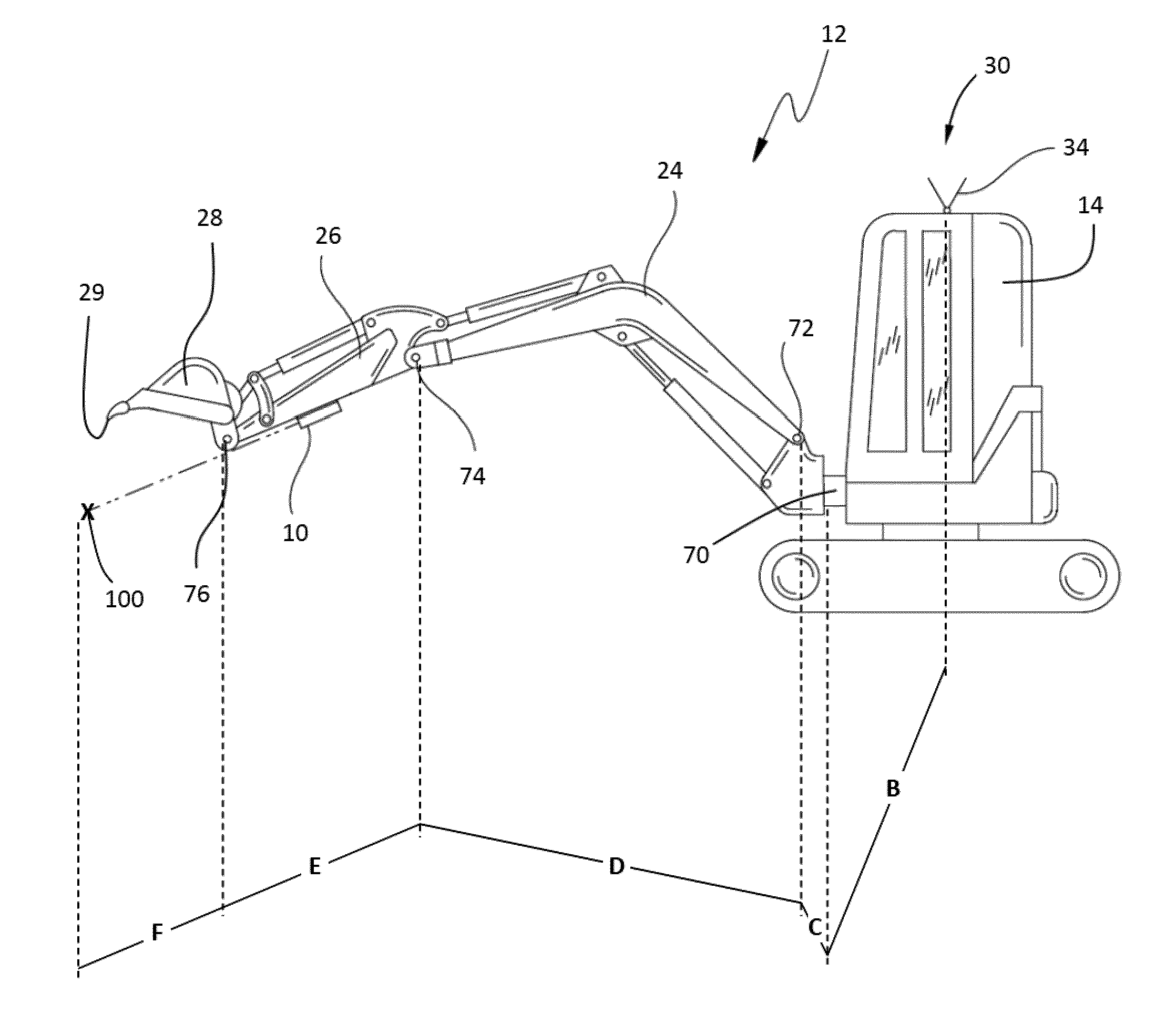
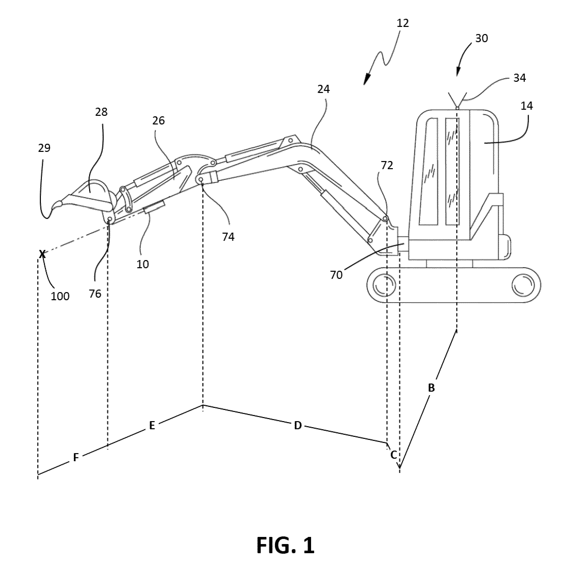
[0025]The present disclosure concerns a combination of an identified topographic feature and an offset to an excavation machine.

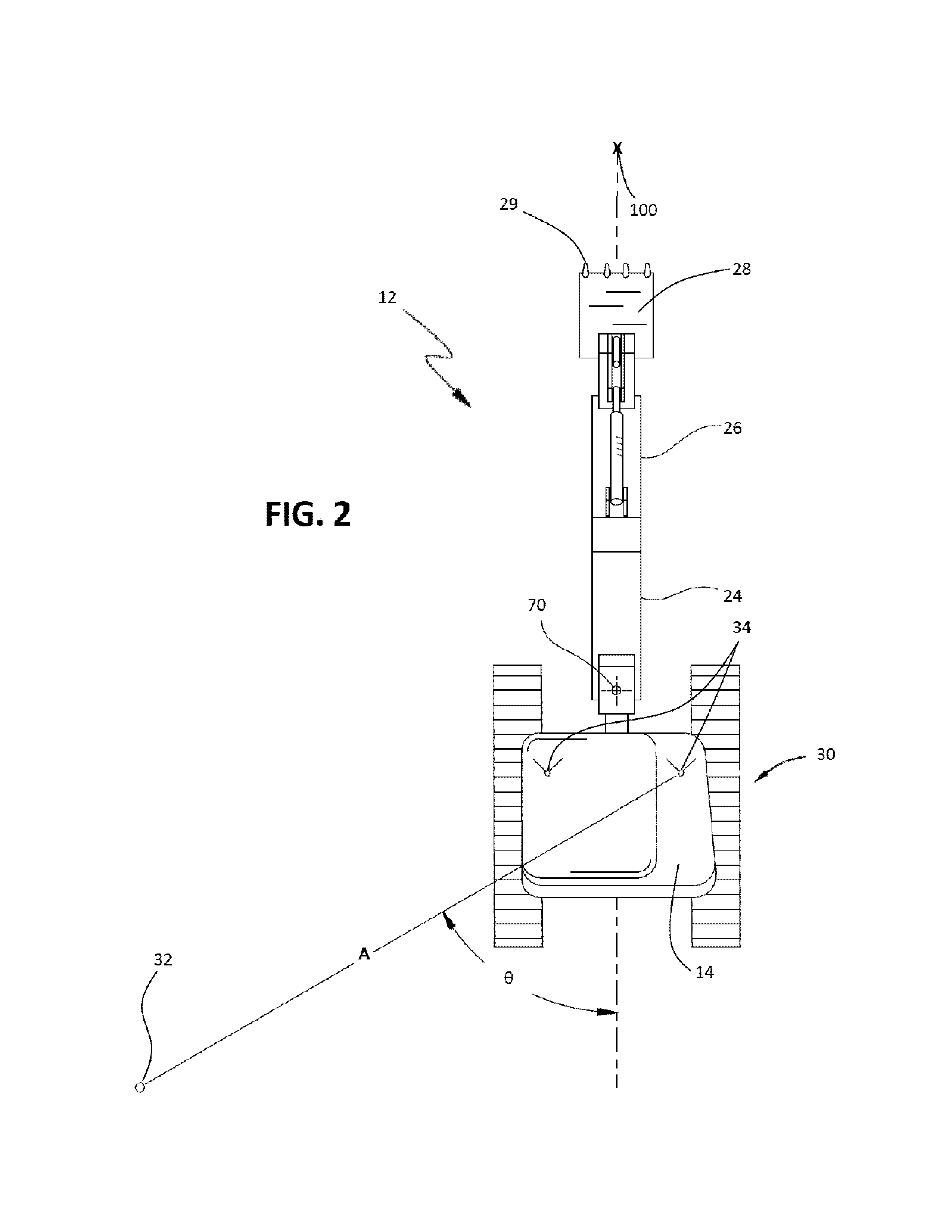
[0026]A further embodiment of the disclosure concerns a further offset from the construction machine to a feature established by a laser range finder affixed to the excavator dipper arm.

[0027]A further embodiment of the disclosure concerns a further offset from construction machine to the feature established by pointing the tool at the feature.

[0028]A further embodiment of the disclosure concerns real time integration of the location of the feature into the data for preparation of as-built drawings.

[0029]A further embodiment of the disclosure concerns collection of data characteristic of topographic features.

[0030]A further embodiment of the disclosure concerns transmitting data characteristic of topographic features to a computer apart from the excavation machine.

[0031]A further embodiment of the disclosure concerns manipulation of data to characterize top...


PUM


Abstract

A combination of location measurement apparatuses to measure in three dimensions the location of an excavator with respect to a job site, and to further measure the location of an excavated or a topographical feature with respect to the excavator by range finding from the excavator in proximity of the feature and contemporaneously recording measurement data on a computer.

Description

CROSS REFERENCE TO RELATED APPLICATION[0001]This application is a continuation-in-part of U.S. patent application Ser. No. 11 / 925,075, filed Oct. 26, 2007, the disclosure of which is hereby expressly incorporated by reference herein in its entirety.FIELD OF THE DISCLOSURE[0002]The present disclosure relates to an earth excavating machine having a means of locating a position on the earth and / or beneath the surface of the earth and recording the same.BACKGROUND OF THE DISCLOSURE[0003]Excavation machines of various descriptions find application in the installation, removal, and repair of below and above ground utilities and structures. Typical below ground utilities include water mains, sewers, conduit for electrical and communications lines, electrical and communications lines installed without conduit, subway transit tunnels, water tunnels and the like.[0004]Below ground installation of utilities such as electrical and communication lines removes the utility lines from the visual ap...

Claims


Application Information

Patent Timeline
IPC IPC(8): E02F3/36G01C21/00E02F3/28
CPCG01C21/04G01S17/06G01S17/88G01S19/07G01C21/20E02F9/264E02F9/261E02F9/245G01S19/53G01S19/072
Inventor MONTGOMERY, JAMES LEONARD
Owner DEERE & CO
Why Eureka
Try Eureka