
Balanced Lift Wind Turbine

Inactive Publication Date: 2011-12-22
CONNER MICHAEL D
View PDF6 Cites 5 Cited by
  • Summary
  • Abstract
  • Description
  • Claims
  • Application Information

AI Technical Summary

Benefits of technology

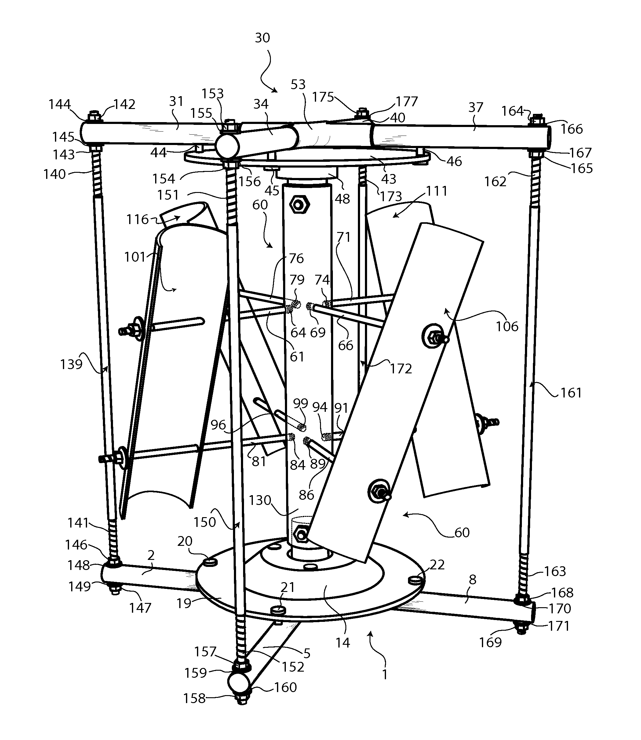
[0003]This invention is a vertical axis wind turbine that uses semi-circular shaped scoops to catch wind energy. This shape minimizes leeward resistance while maximizing windward collection. In addition, the scoops are distinctively angled so updrafts can be caught. This angle makes the invention uniquely suited for mounting on buildings along the peak of slopped roofs, or the perimeter of flat roofs, where wind currents are increased. Due to the weight of the apparatus and the affects of wind flow, all other vertical axis wind turbines weigh down or torque the motor shaft which dampens the ability to harness wind energy. The present invention overcomes this problem by introducing a top bearing and frame structure to lower any resistance that the motor shaft may experience. With less resistance from the frame and increased wind collection from the scoops, the present invention is able to maximize the energy harnessed from wind.

Problems solved by technology

Due to the weight of the apparatus and the affects of wind flow, all other vertical axis wind turbines weigh down or torque the motor shaft which dampens the ability to harness wind energy.

Method used


Image

  • Balanced Lift Wind Turbine
  • Balanced Lift Wind Turbine
  • Balanced Lift Wind Turbine

Examples


Embodiment Construction

[0016]All illustrations of the drawings are for the purpose of describing selected versions of the present invention and are not intended to limit the scope of the present invention.

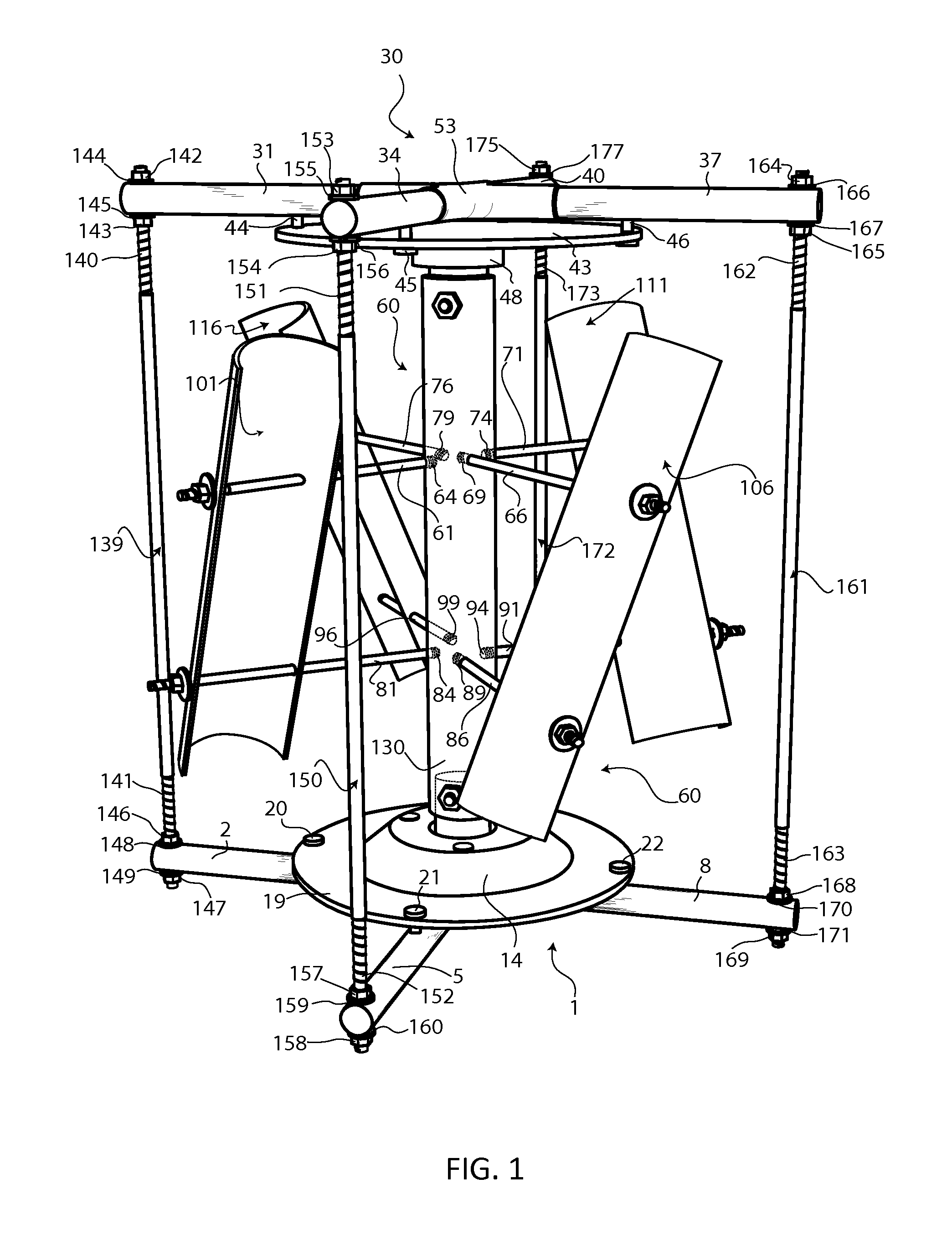
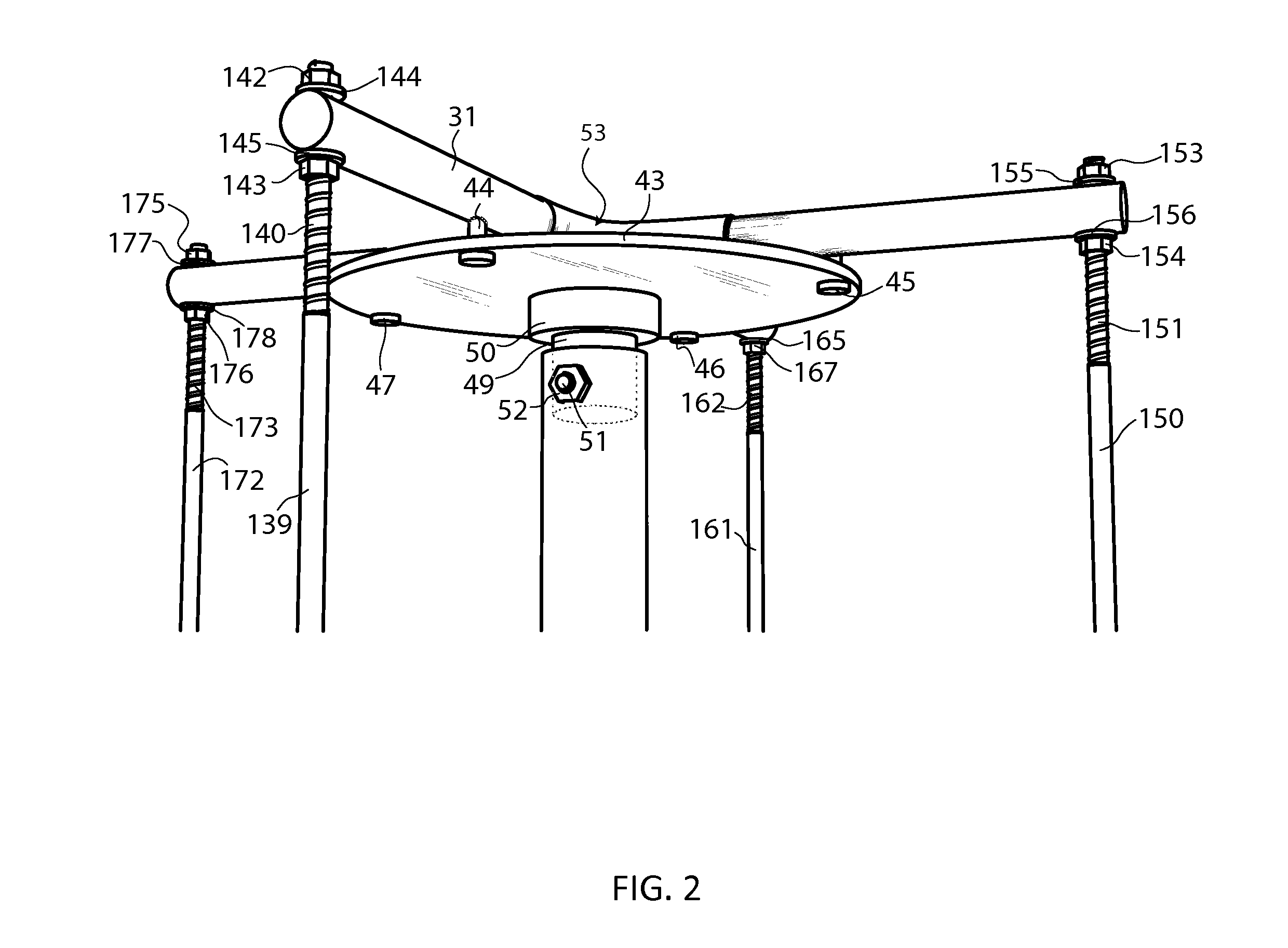
[0017]In reference to FIG. 1, the Balanced Lift Wind Turbine comprises of separate main sections including a base 1, a top 30, a scoop support 60, a first frame support 139, a second frame support 150, a third frame support 161, and a fourth frame support 172.

[0018]In reference to FIG. 1, FIG. 5, FIG. 6, and FIG. 7, the base 1 comprises of sub-components including a first footer 2, a second footer 5, a third footer 8, a fourth footer 11, a generator 14, at least one generator fastener 18, a base plate 19, a first base bolt 20, a second base bolt 21, a third base bolt 22, a fourth base bolt 23, and a base fixture 24. The first footer 2 comprises of a first footer fixture threaded end 3 and a first footer support hole 4. The second footer 5 comprises of a second footer fixture threaded end 6 and a second f...


PUM


Abstract

A vertical axis wind turbine that utilizes a unique semi-circular, angled, scoop design and frame to fully harness wind energy. The shape of the scoops maximizes wind collection while minimizing wind resistance. The angle of the scoops allows the wind turbine to catch wind, including updrafts, to produce a rotational and balanced lifting force on the scoop system. This balanced lift is possible due to a stable frame which maintains a fixed position of the vertical axis.

Description

FIELD OF THE INVENTION[0001]The invention relates generally to a wind turbine that is able to generate electrical power from wind energy. It is the object of the present invention to effectively and efficiently harness the winds energy for converting into electrical energy.BACKGROUND OF THE INVENTION[0002]The most common wind turbines today make use of a horizontal axis motor shaft to harness mechanical energy and transform it into electrical energy. Other wind turbines make use of a vertical axis motor shaft to harness wind energy without needing to be turned into the wind. Nearly all current wind turbines employ airfoil shaped blades to catch wind energy.[0003]This invention is a vertical axis wind turbine that uses semi-circular shaped scoops to catch wind energy. This shape minimizes leeward resistance while maximizing windward collection. In addition, the scoops are distinctively angled so updrafts can be caught. This angle makes the invention uniquely suited for mounting on bu...

Claims


Application Information

Patent Timeline
IPC IPC(8): F03D11/02F03D3/00F03D9/00
CPCF03D3/061Y02E10/74F05B2240/211F03D3/064
Inventor CONNER, MICHAEL D.
Owner CONNER MICHAEL D
Learn More