Mobile communication device, communication method, integrated circuit, and program

a communication device and mobile technology, applied in the field of mobile communication devices, can solve the problems of affecting the widespread use of the home network, the difficulty of initial setting of the network on white goods without display devices and input devices, etc., and achieves the effect of simple operation, low cost and simple operation

Active Publication Date: 2011-12-22
PANASONIC INTELLECTUAL PROPERTY CORP OF AMERICA
View PDF5 Cites 163 Cited by
  • Summary
  • Abstract
  • Description
  • Claims
  • Application Information

AI Technical Summary

Benefits of technology

[0025]The mobile communication device according to the present invention enables the user to complete setting necessary for a home network, without a complex operation.
[0026]The transmission information can be transmitted by a simple operation such as merely touching the mobile communication device to the installed appliance.
[0027]The device used here is a mobile communication device such as a mobile phone, with there being no need to add a new structure for proximity wireless communication. This contributes to a lower cost.
[0028]In addition, the device used here is a mobile communication device, with there being no need to add a new structure for obtainment of position information. This contributes to a sufficiently lower cost. That is, an extent of cost reduction can be increased.
[0029]For instance, there is no need to add a GPS device (new structure) to the installed appliance.
[0030]A very complex operation required to perform suitable wireless communication, such as an operation of wireless communication power setting, becomes unnecessary, as a simple operation such as a touching operation is sufficient. Thus, a significantly simplified operation can be realized.

Problems solved by technology

However, it is extremely difficult to perform initial setting of a network on white goods having no display device and input device.
This difficulty in performing setting necessary for various services hampers the widespread use of the home network.

Method used


Image

  • Mobile communication device, communication method, integrated circuit, and program
  • Mobile communication device, communication method, integrated circuit, and program
  • Mobile communication device, communication method, integrated circuit, and program

Examples


embodiment a

[0249]A communication device according to Embodiment A (Embodiments A1 to A13) may be a subordinate conception of the following communication device X (e.g. FIGS. 132, 135, 115, 116, 127).

[0250]The communication device X is a communication device (e.g. a mobile device N20 in FIGS. 135 and 132, a communication device Y02 in FIG. 127, a communication device M1101 in FIGS. 115 and 116, a communication device M1101S or M1101R in FIG. 120) that reads terminal device information from a terminal device (e.g. the TV N10A in FIGS. 134 and 135, a terminal device Y01 in FIG. 127) by proximity wireless communication (RF tag communication), and transmits the read terminal device information to a server apparatus (a registration server N40 in FIGS. 135 and 133, a server Y04 in FIG. 127) via a general-purpose network (a home network N100 or an external network N101 in FIG. 135). In detail, the communication device X includes: a terminal device information obtainment unit (a RF-ID reader / writer N21...

embodiment a1

[0269]Embodiment A1 is described below.

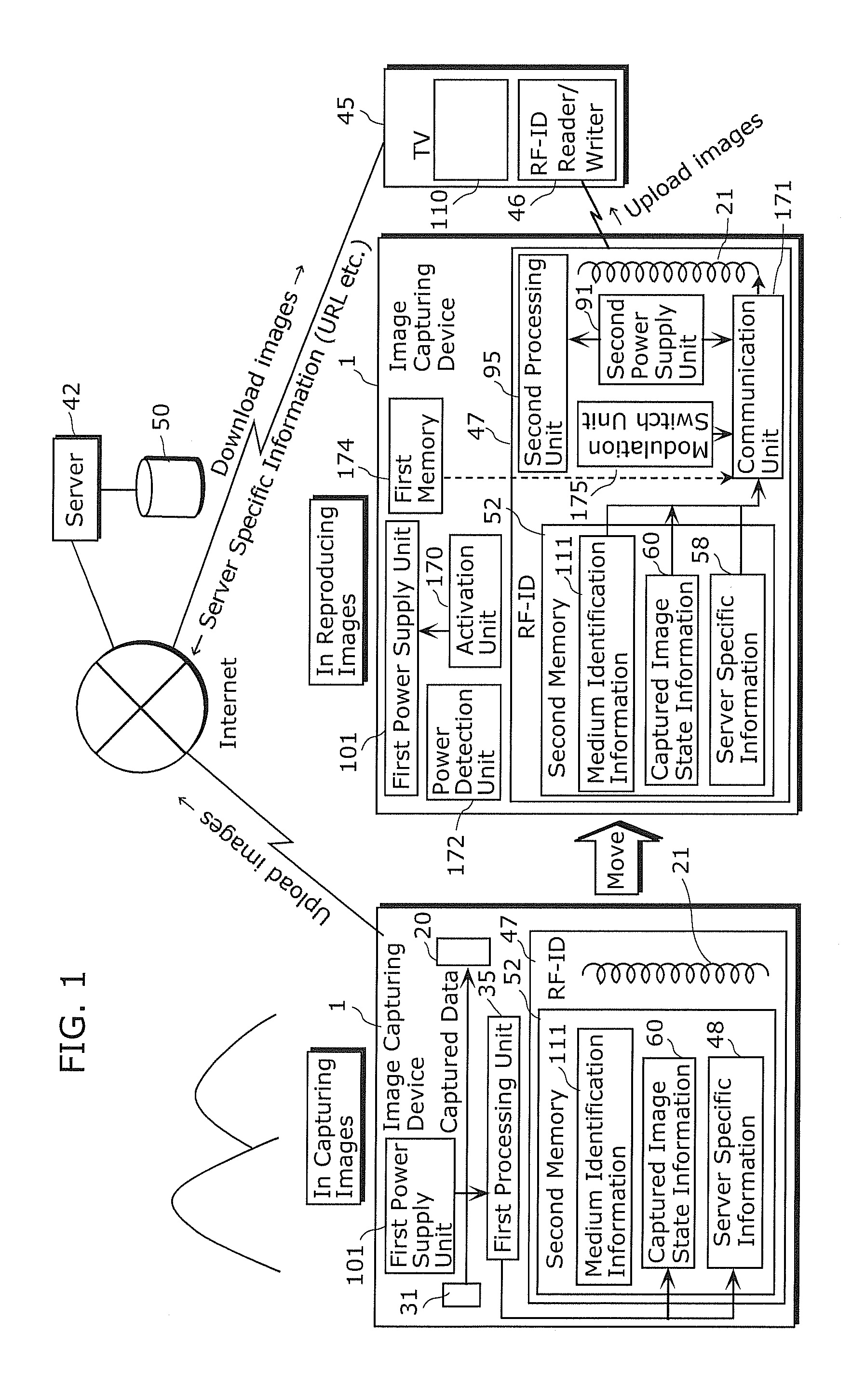
[0270]FIG. 1 is a schematic diagram of Embodiment A1.

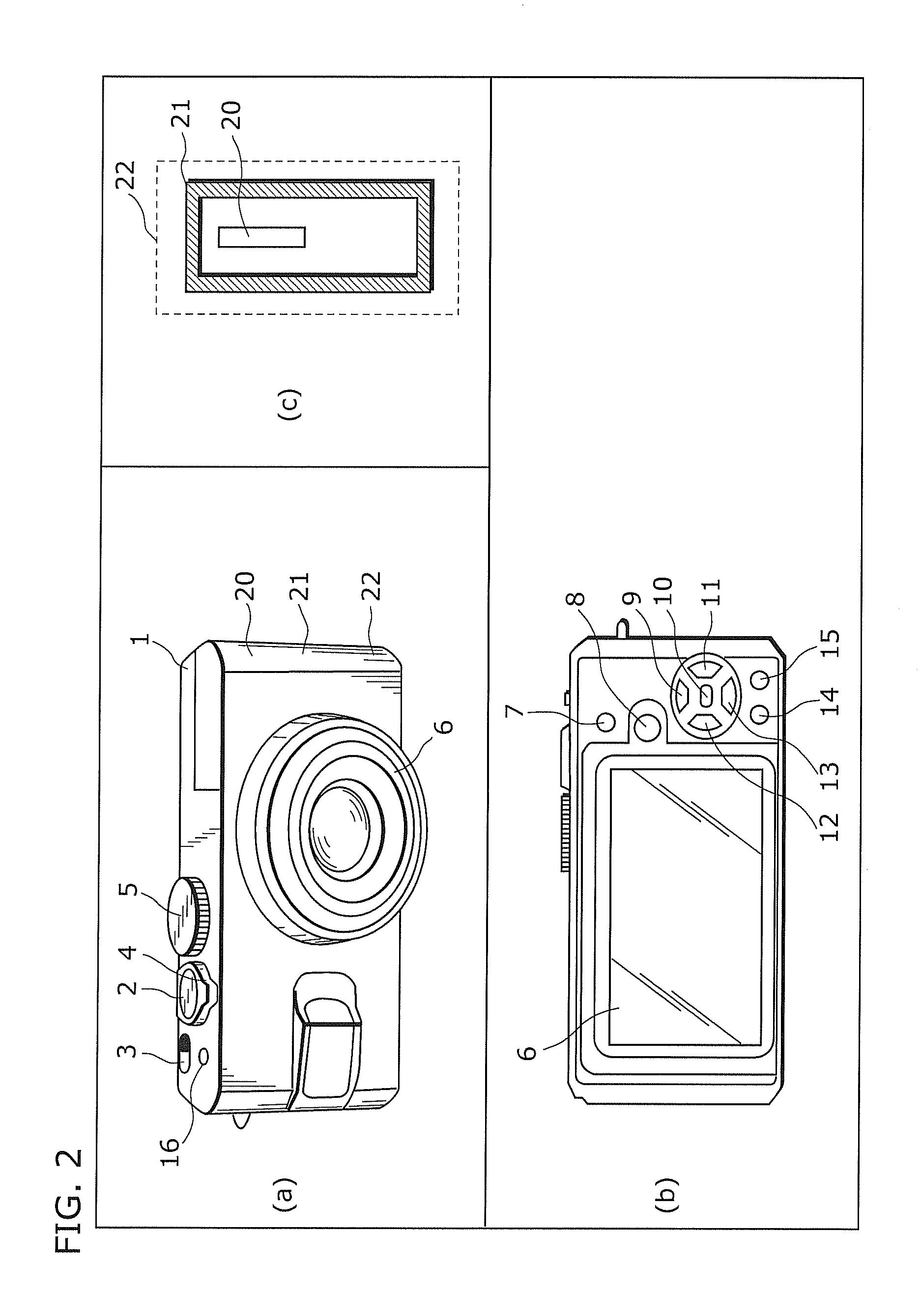
[0271]Here, a communication system including an image capturing device (camera) 1 (a communication device 9A1), a TV 45, and a server (image server) 42 is illustrated. In FIG. 1, the image capturing device 1 capturing images is illustrated on a left-hand side, while the image capturing device 1 reproducing the captured images is illustrated on a right-hand side.

[0272]The image capturing device 1 is an example of the communication device according to the aspect of the present invention. Here, the image capturing device 1 is implemented as a digital camera.

[0273]For units used in capturing images (see the left-hand side in FIG. 1), the image capturing device 1 includes a first power supply unit 101, a video processing unit 31, a second antenna 20, a first processing unit 35, a second memory 52, and a RF-ID antenna 21. The second memory 52 holds medium identification information 111, captured im...

embodiment a2

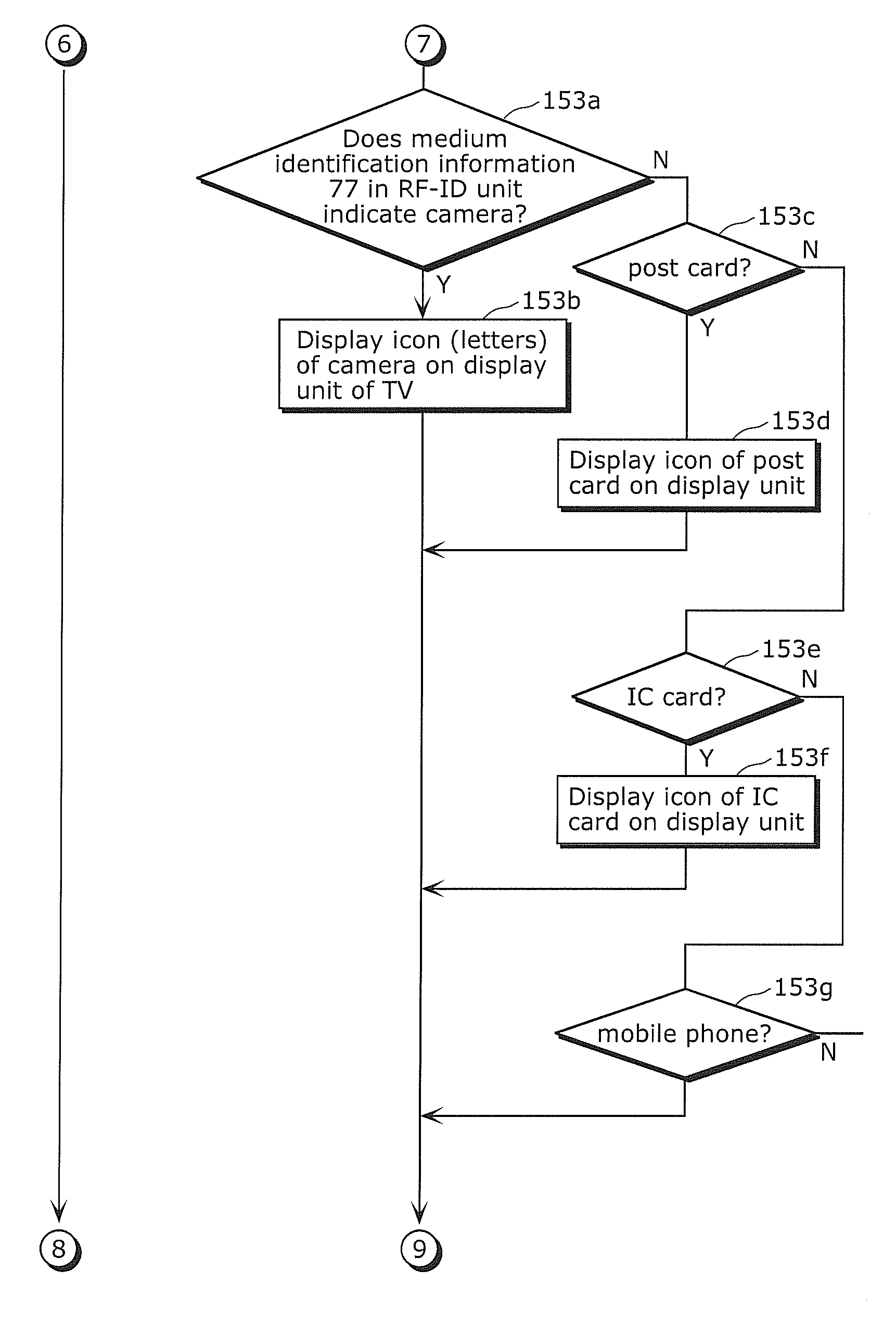
[0523]Embodiment A2 of the present invention is described below. In Embodiment A2, actual operations of the communication system are described. In the communication system, images captured by a camera are uploaded to a server, and then downloaded by a simple operation to a TV to be displayed. The whole configuration of the communication system according to Embodiment A2 is the same as that of the communication system according to Embodiment A1.

[0524]FIG. 40 (FIGS. 40A, 40B, and 40C) is a flowchart of uploading steps in a camera according to Embodiment A2.

[0525]As noted above, the whole drawing including FIGS. 40A to 40C is simply referred to as “FIG. 40” when necessary.

[0526]The same applies to FIG. 42 and the like.

[0527]FIG. 40 is a flowchart of processing performed by a camera (the image capturing device 1) to upload photographs (images). First, the camera captures images (Step S5101). Then, the captured images are stored into the third memory (Step S5102). Then, the camera update...


PUM


Abstract

A mobile communication device (98b) includes: an appliance information obtainment unit (98n) that obtains appliance information (98n1) by proximity wireless communication (98c1) with an appliance (98a) installed in a home (99), the appliance information specifying the appliance (98a); a position information obtainment unit (98j) that obtains position information (98j1) of the mobile communication device when the proximity wireless communication (98c1) is performed; and a transmission unit (98o) that transmits transmission information (98o1) to a server (98c) in the case where the proximity wireless communication (98c1) is performed, the transmission information including the appliance information (98n1) and the position information (98j1).

Description

TECHNICAL FIELD[0001]The present invention relates to a mobile communication device that includes a reader / writer of proximity wireless communication and a general-purpose communication means.[0002]The present invention also relates to a mobile communication device that includes a reader / writer of proximity wireless communication and a general-purpose communication means and facilitates setting in a home network.BACKGROUND ART[0003]High expectations are placed on a Home Energy Management System (HEMS) that networks and automatically controls energy consuming appliances in a home, such as home appliances and water heaters. Moreover, as studies for home appliance traceability, daily life watching services, and the like have started, a home network including white goods is expected to come into widespread use. However, it is extremely difficult to perform initial setting of a network on white goods having no display device and input device. This difficulty in performing setting necessa...

Claims


Application Information

Patent Timeline
Patent Type & Authority Applications(United States)
IPC IPC(8): H04W88/02H04W4/80
CPCH04L12/40013H04W4/008H04W64/003H04B5/0062G08C2201/93G08C2201/32G08C2201/91G08C17/02G08C2201/20H04W4/80
Inventor MATSUSHITA, YOSUKEYAMAOKA, MASARUOHTSUBO, SHOHJIMUKAI, TSUTOMUNAKAE, HIRONORIOSHIMA, MITSUAKI
Owner PANASONIC INTELLECTUAL PROPERTY CORP OF AMERICA
Why Eureka
Try Eureka