Communication system and radio processing apparatus

a radio processing and communication system technology, applied in the field of communication system and radio processing apparatus, can solve the problems of affecting the business deployment of telecommunications companies, radio resources that may be effectively utilized within a specific frequency range (or frequency band) are limited, and communication via radio waves may consume radio resources

Inactive Publication Date: 2011-12-22
FUJITSU LTD
View PDF4 Cites 0 Cited by
  • Summary
  • Abstract
  • Description
  • Claims
  • Application Information

AI Technical Summary

Problems solved by technology

The communication via the radio waves may consume radio resources.
That is, the radio resources that may be effectively utilized within a specific frequency range (or frequency band) are limited.
The former method may involve a long-term deliberation for the new frequency allocation or a large investment for securing the frequencies, which may affect the business deployment of the telecommunications companies.
The latter method may involve the reduction in the frequency bands already available for the existing services, which may decrease the number of users of the existing services in the existing system or the degradation of service quality.
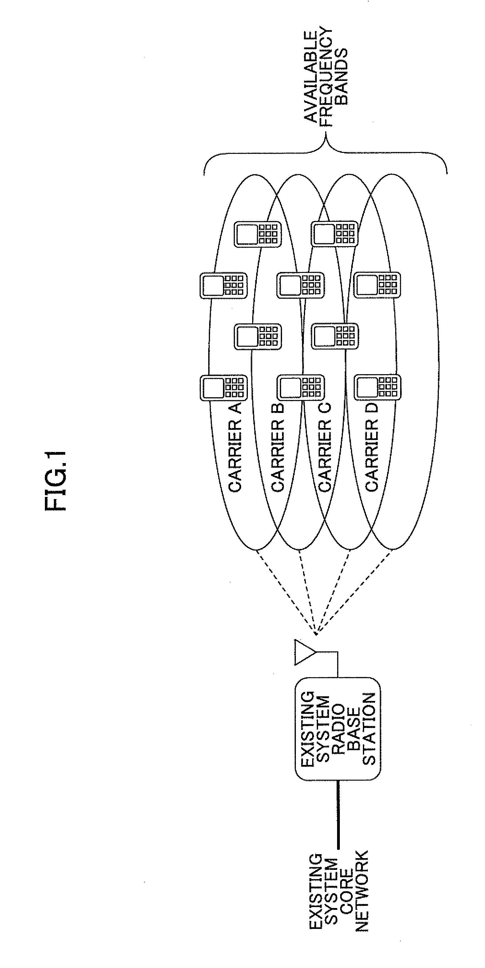
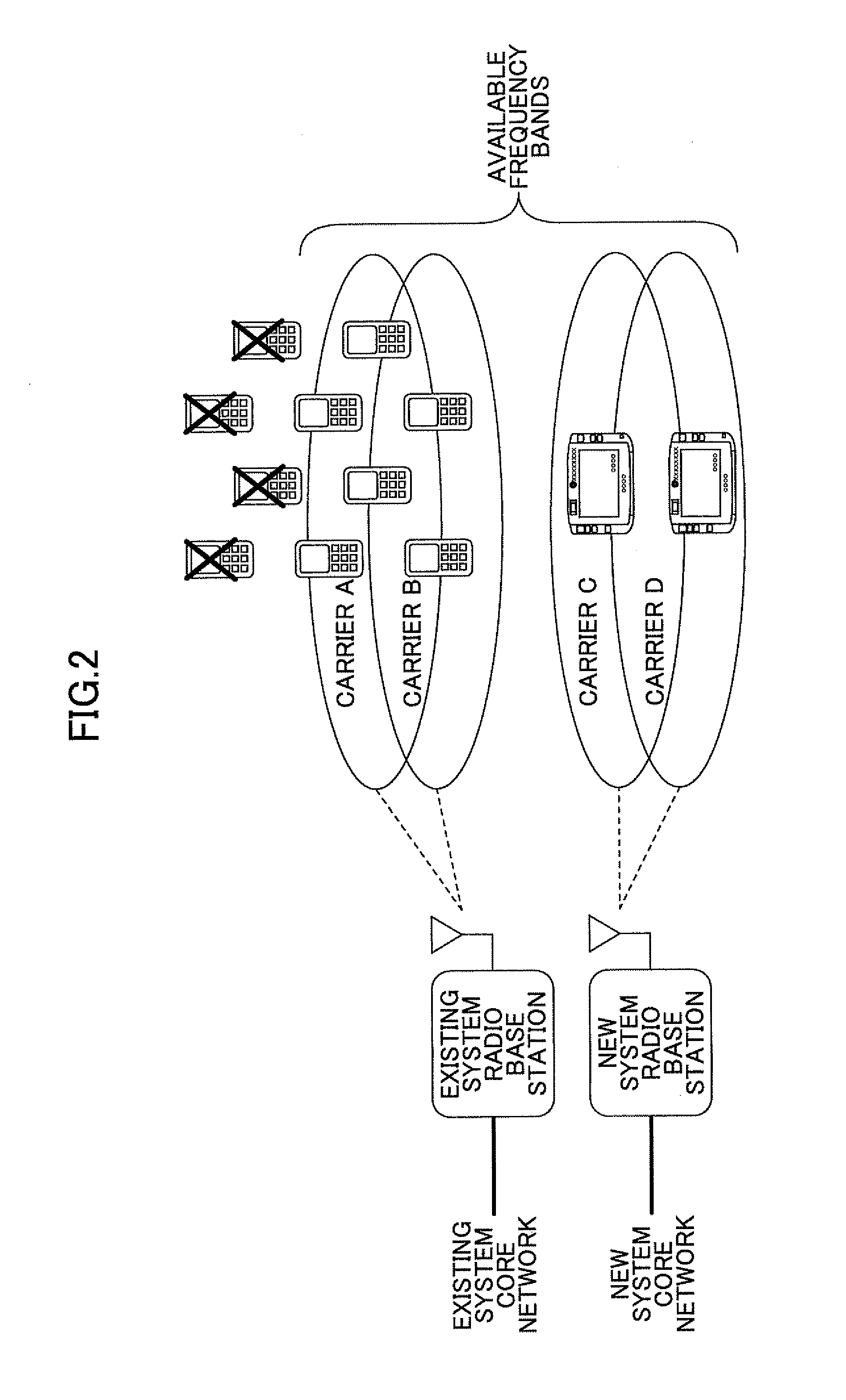
However, after the relocating some (i.e., carriers C and D in this case) of the carriers to the new system, the existing service providing area may merely support up to 40 users, thereby imposing an adverse effect on the existing system.

Method used


Image

  • Communication system and radio processing apparatus
  • Communication system and radio processing apparatus
  • Communication system and radio processing apparatus

Examples


first embodiment

Operation of First Embodiment

[0048]In the configuration illustrated in FIG. 5, the existing call processing section 11a and the new system call processing section 13a each monitor the statuses of the carriers A, B, C, and D, and start operating when they acknowledge that the carriers A, B, C, and D are available. The carrier status generating circuit 27 in the shared radio processing apparatus 15 allocates the carriers C and D to the existing system radio base station apparatus 12 and the carriers A and B to the new system radio base station apparatus 13, and initiates the operation based on such initial allocation statuses of the carriers A, B, C, and D. The initial allocation statuses of the carriers A, B, C, and D are also supplied to the comparator 28.

[0049]When the existing system radio base station apparatus 12 and the new system radio base station apparatus 13 start up and establish connections between the circuits within the respective radio base station apparatuses 12 and 1...

second embodiment

Operation of Second Embodiment

[0090]FIG. 8 is a flowchart illustrating processing including steps executed by the monitoring control section 46 (i.e., “C & M”) in FIG. 7. In this processing, the users of the carrier subject to system reallocation may be shifted to another carrier by utilizing the handover function. Similar to the initial status of the first embodiment, the carriers A and B are allocated to the new system, while the carriers C and D are allocated to the existing system. Note that in this initial status, the attenuator circuit 51 has not lowered the radio output power.

[0091]Similar to the processing of the first embodiment, when a decrease in a communication amount is detected in the new system while an increase in a communication amount is detected in the existing system, the monitoring control section 46 determines whether it has received from the carrier status generating circuit 47 a report indicating that the carrier B (or carrier A) is no longer available to the...


PUM


Abstract

A communication system for performing communication between different mobile terminals in different mobile communication systems by allocating different carriers to the mobile communication systems. The communication system includes a shared radio processing apparatus that is shared by the different mobile communication systems and performs radio processing for the different mobile communication systems. The shared radio processing apparatus includes a measuring unit for measuring power of the carriers, a carrier usage determination unit for determining the frequency of carrier usage based on measured values of the carriers, a carrier status determination unit for determining a carrier status indicating whether to allocate one of the carriers to one of the mobile communication systems based on the carrier usage, and a reporting unit for transmitting a carrier status report including the carrier status to the respective mobile communication systems.

Description

CROSS-REFERENCE TO RELATED APPLICATIONS [0001]This patent application is based upon and claims the benefit of priority of the prior Japanese Patent Application No. 2010-140856 filed on Jun. 21, 2010, the entire contents of which are incorporated herein by reference.FIELD [0002]A certain aspect of the embodiments discussed herein is related to a communication system and a radio processing apparatus.BACKGROUND [0003]With the strategy of service providers of telecommunications companies and the development of technology, mobile communication systems have been replaced by new ones at intervals of several years to decades to provide new services. For example, 1-G mobile communication systems from the late 1980s to the early 1990s provided services for analog mobile terminals, mainly providing voice services, which were then replaced by 2-G mobile communication systems. 2-G mobile communication systems from the mid-1990s have provided digital voice communication services such as Personal ...

Claims


Application Information

Patent Timeline
Patent Type & Authority Applications(United States)
IPC IPC(8): H04W24/02
CPCH04W36/30H04W16/14
Inventor HAMADA, YUTAKA
Owner FUJITSU LTD
Why Eureka
Try Eureka