Tilt Stabilizing Accommodating Intraocular Lens

a technology of tilt stabilization and intraocular lens, which is applied in the field of tilt stabilization accommodating intraocular lens, can solve the problems of destabilizing the lens optic, unable to allow adequate movement of the optics, and complication can occur, so as to improve near vision, improve stability, and reduce resistance to pressure changes

Inactive Publication Date: 2011-12-22
CUMMING JAMES STUART
View PDF17 Cites 46 Cited by
  • Summary
  • Abstract
  • Description
  • Claims
  • Application Information

AI Technical Summary

Benefits of technology

[0014]One feature of the presently described AIOL is that the connecting members operate to stabilize the optic with respect to the plate haptics. Coupling the haptics to the optics with spaced apart connecting members permits pressure to be distributed more evenly along more of the circumference of the optic and thus increases optic stability. Whereas a single narrow connecting member on opposing sides of the optic may cause the lens to tilt easily during fibrosis.
[0015]Another feature of the presently described AIOL is that the connecting members improve near vision by reducing the resistance to pressure changes on the optic with contraction and relaxation of the ciliary muscle. This occurs because the spaces between the connecting members do not allow the connecting members to ‘share’ force. Furthermore, the connecting members preferably comprise one or more grooves or hinges on one or more opposing surfaces. These grooves or hinges further decrease the resistance of the connecting member to pressure changes caused by the contracting and relaxing ciliary muscle.

Problems solved by technology

When the accommodating lens plate haptic is fibrosed into the capsular bag of an eye after cataract surgery, sometimes several weeks or months following the surgery, a complication can occur.
However, these designs do not permit adequate movement of the optic to a change in vitreous cavity pressure to allow many patients to read comfortably at near without glasses.
However, elongating the hinge base would destabilize the lens optic, and making the hinge narrower would make it prone to tilting.

Method used


Image

  • Tilt Stabilizing Accommodating Intraocular Lens
  • Tilt Stabilizing Accommodating Intraocular Lens
  • Tilt Stabilizing Accommodating Intraocular Lens

Examples


Embodiment Construction

[0012]An accommodating intraocular lens design according to an embodiment of the present invention is described that overcomes the deficiencies of present designs noted above.

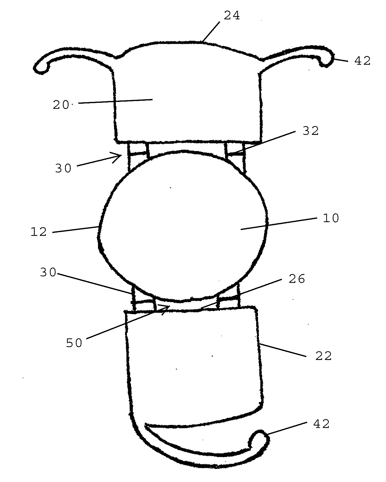
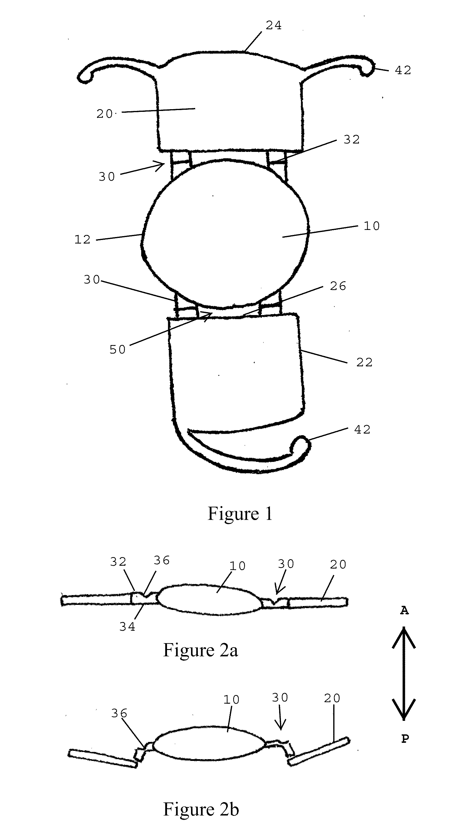
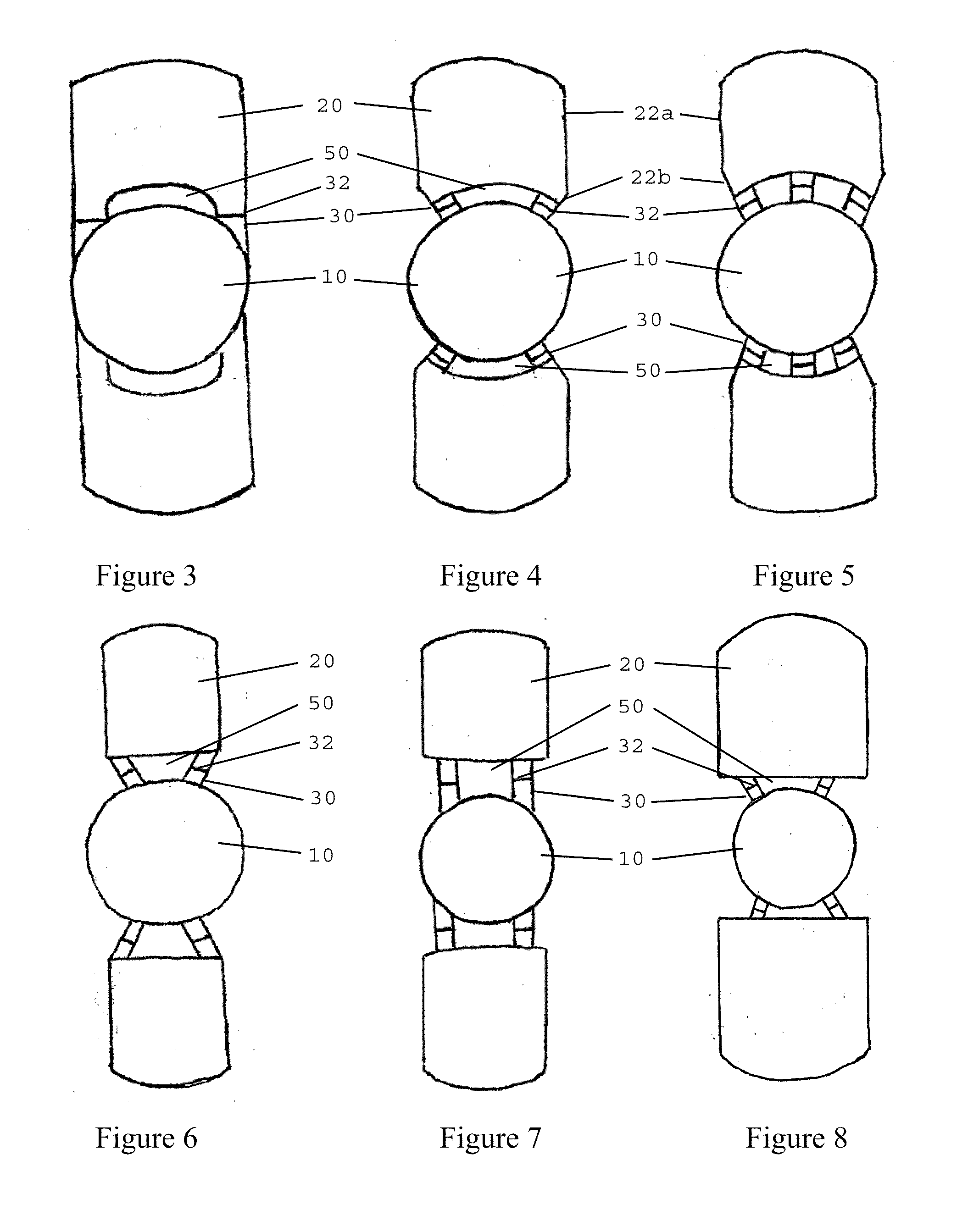
[0013]An accommodating intraocular lens (AIOL) is provided whereby an optic is coupled to opposing plate haptics by a plurality of spaced apart flexible connecting members.

[0014]One feature of the presently described AIOL is that the connecting members operate to stabilize the optic with respect to the plate haptics. Coupling the haptics to the optics with spaced apart connecting members permits pressure to be distributed more evenly along more of the circumference of the optic and thus increases optic stability. Whereas a single narrow connecting member on opposing sides of the optic may cause the lens to tilt easily during fibrosis.

[0015]Another feature of the presently described AIOL is that the connecting members improve near vision by reducing the resistance to pressure changes on the optic with contractio...


PUM


Abstract

An intraocular lens for insertion into a capsular bag of an eye. A plurality of flexible connecting members couples a lens optic to a pair of opposing of plate haptics. The coupling members stabilize the optic with respect to the haptics. The coupling members are spaced apart straps having grooves that increase lens response to changes in vitreous pressure.

Description

CROSS-REFERENCE TO RELATED APPLICATIONS[0001]This application is based on and claims the benefit of the filing of U.S. Provisional Patent Application No. 61 / 398,107 filed Jun. 21, 2010; U.S. Provisional Patent Application No. 61 / 398,098 filed Jun. 21, 2010; U.S. Provisional Patent Application No. 61 / 398,115, filed Jun. 21, 2010; and U.S. Provisional Patent Application No. 61 / 398,099, filed Jun. 21, 2010, the contents and disclosure of which are fully incorporated herein by reference.[0002]This application is related to U.S. Non-Provisional patent application Ser. No. 13 / 017,189, filed Feb. 14, 2011; and U.S. Non-Provisional patent application Ser. No. 13 / 092,359, filed Apr. 22, 2011, the contents and disclosure of which are fully incorporated herein by reference.BACKGROUND OF THE INVENTION[0003]Accommodating Intraocular Lenses were developed in the early 1900's and have been sold in Europe for the last ten years and later in the U.S. They function by means of forward movement of the...

Claims


Application Information

Patent Timeline
Patent Type & Authority Applications(United States)
IPC IPC(8): A61F2/16
CPCA61F2/1613A61F2/1624A61F2002/1689A61F2002/1683A61F2002/1682A61F2220/0091A61F2250/0018A61F2/1629A61F2002/169A61F2002/16905A61F2002/1681A61F2230/0006A61F2230/0069A61F2/16
Inventor CUMMING, JAMES STUART
Owner CUMMING JAMES STUART
Why Eureka
Try Eureka