Touch safe fuse module with improved wiring lugs

Active Publication Date: 2011-12-29
EATON INTELLIGENT POWER LIMITED
View PDF3 Cites 2 Cited by
  • Summary
  • Abstract
  • Description
  • Claims
  • Application Information

AI Technical Summary

Benefits of technology

[0008]The wiring lug according to the invention comprises a fuse clip that receives a fuse contact and a pressure plate that couples to an electrical conductor. A box lug moves with respect to the pressure plate to crimp the conductor between an interior of the box lug and the pressure plate. The crimping in this fashion can provide an increased area of electrical contact between the conductor and the pressure plate. One or more projections formed in the pressure plate can increase a holding strength of the wiring lug on the conductor. The projections also can maintain alignment of the pressure plate and the box lug by mating with corresponding apertures in the box lug. This wiring lug may be used in fuse holders as described below.
[0011]In accordance with yet another aspect of the invention, the fuse clip member may be formed from a single piece of conductive material. The fuse clip member formation beings with a primary member. A piece of the primary member that is substantially rectangular and located in the center of the primary member is split away on all but one side, forming a secondary member. The distal end of the secondary member is rotated such that at least a portion of the secondary member is substantially perpendicular to the primary member. The secondary member is configured to become the pressure plate. The primary member is then bent to form a fuse clip by disposing two ends of the primary member adjacent to each other. A spring is disposed around the two ends of the primary member to bias the two ends towards each other. This method of creating a fuse clip member allows for minimal generation of waste, while creating a single member that can receive a fuse contact and can act as a pressure plate used as an electrical conductor contact.

Problems solved by technology

These previous methods led to problems with heat transfer and electrical resistance.
Additionally, high torque is needed to secure the electrical leads to the screw terminals, which is a problem in itself and which may damage the leads.
Additional features of previous embodiments included securing devices that have congruent teeth flanking either side of the electrical lead, leading to the possibility of damaging the leads during installation.
An additional problem with conventional lugs relates to the conductive materials used in wiring lugs.
In addition to the expense associated with such conductive materials, there is usually an amount of ‘scrap’ conductive material that is unused.
This excess material has been undesirable as these devices used special copper alloys that are expensive.
The use of these copper alloys also leads to the additional problem of requiring a hydraulic press because the conductive material is too strong to be manipulated with hand tools, thereby further increasing manufacturing costs.

Method used


Image

  • Touch safe fuse module with improved wiring lugs
  • Touch safe fuse module with improved wiring lugs
  • Touch safe fuse module with improved wiring lugs

Examples


Embodiment Construction

[0027]The invention may be better understood by reading the following description of non-limitative, exemplary embodiments with reference to the attached drawings wherein like parts of each of the figures are identified by the same reference characters.

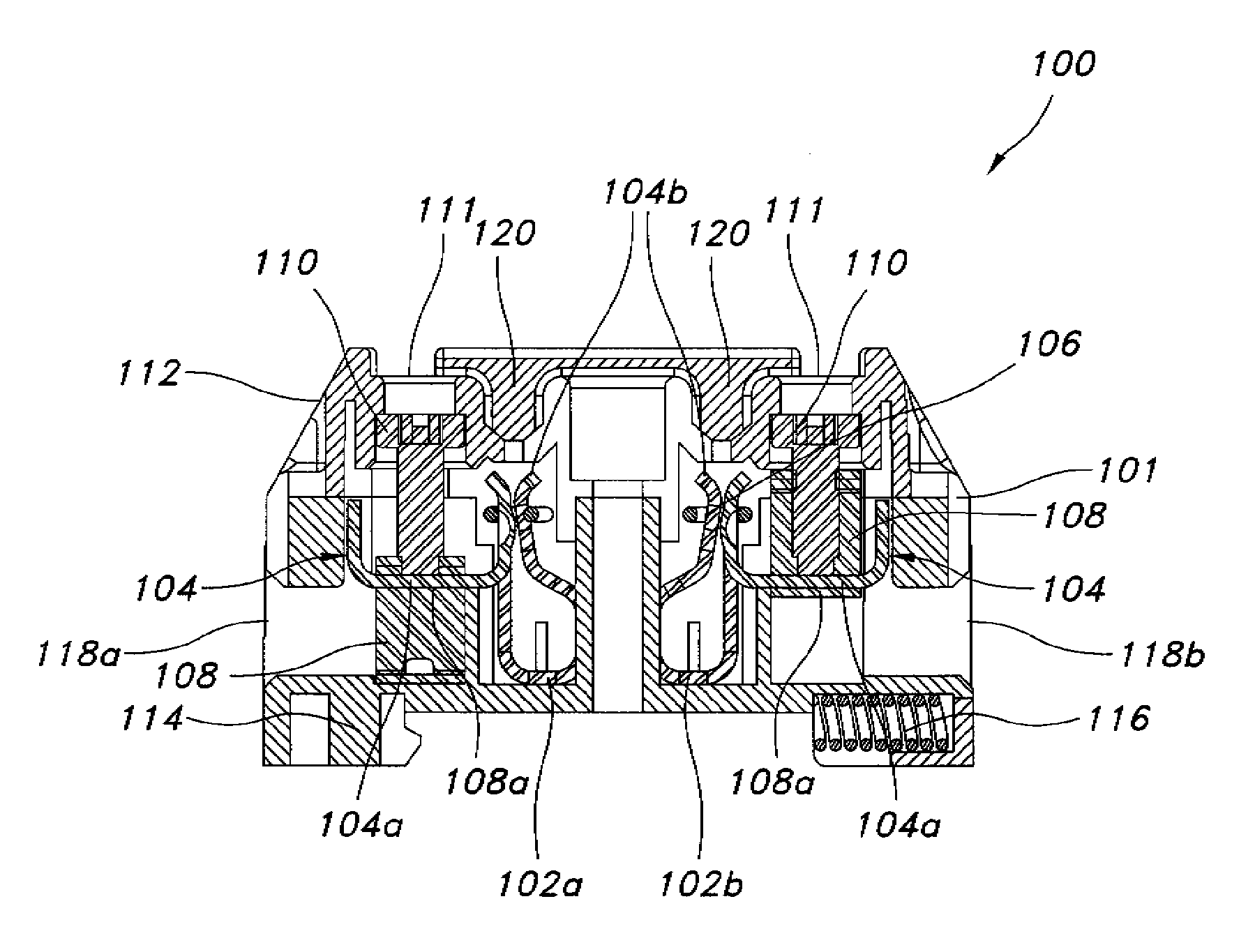
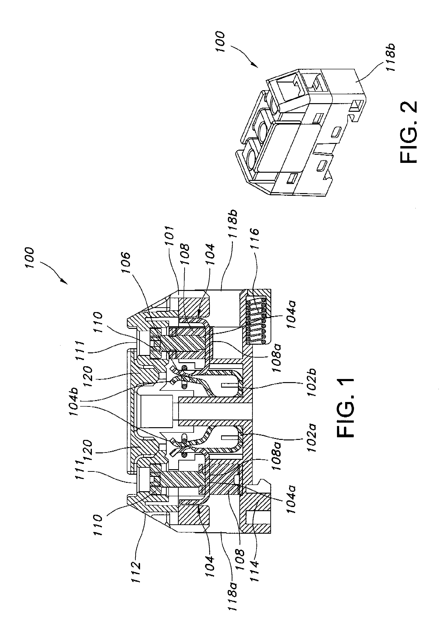
[0028]With reference to FIGS. 1 and 2, an exemplary embodiment of a wiring lug disposed in a fuse module will be described. FIG. 1 is a cross sectional view of a fuse module 100 that utilizes two wiring lugs 102 (illustrated separately as wiring lugs 102a and 102b and collectively or individually referred to as wiring lugs 102) according to one exemplary embodiment of the invention. FIG. 2 is a perspective view of the exemplary fuse module 100 illustrated in FIG. 1.

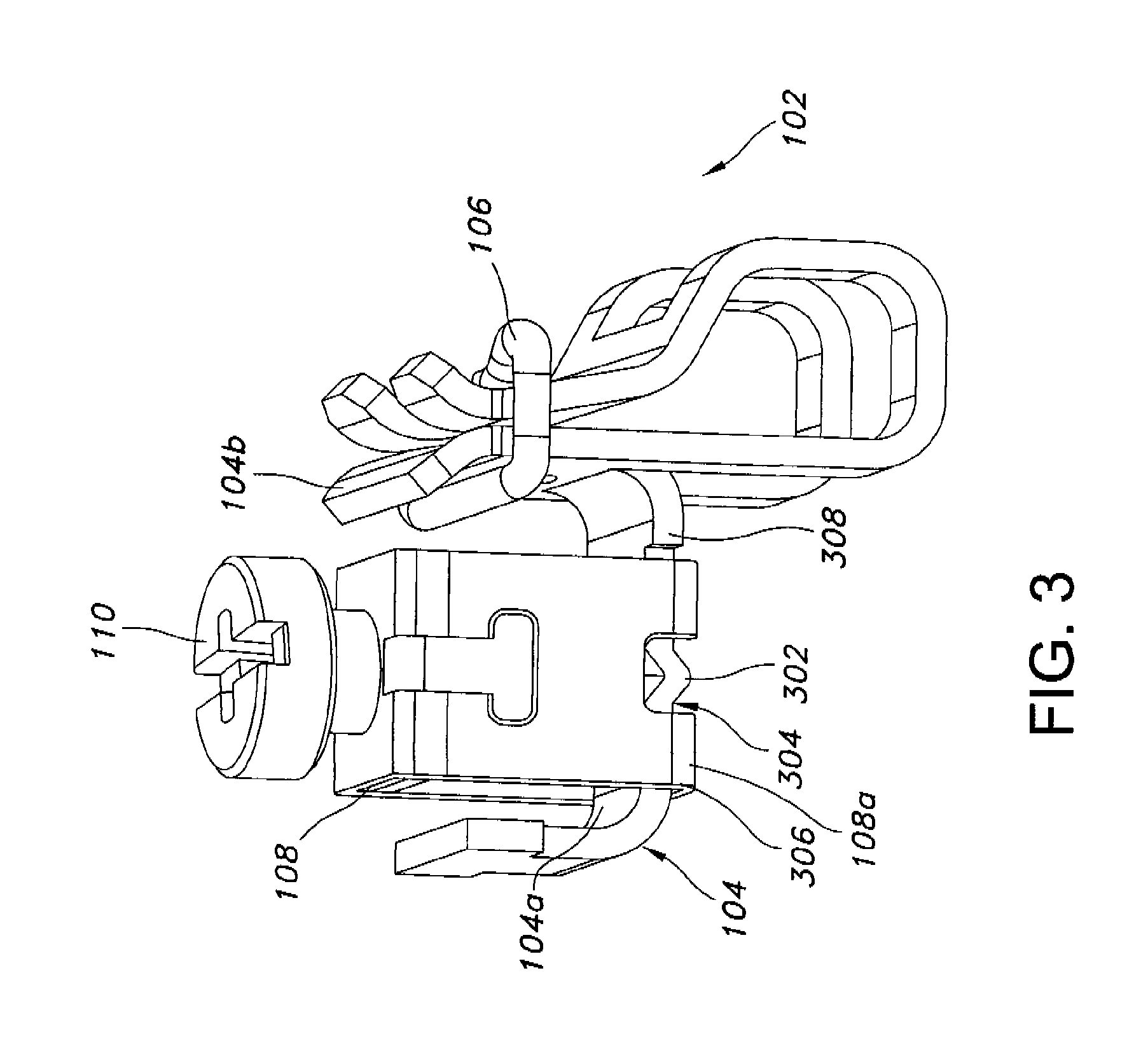
[0029]Referring to FIG. 1, the fuse module 100 comprises a housing 101 in which the two wiring lugs 102a, 102b are disposed. The housing 101 is suitably formed to hold the wiring lugs 102a, 102b in position with respect to each other. Each of the wiring lugs 102 comprises a...


PUM

PropertyMeasurementUnit
Pressureaaaaaaaaaa
Electrical conductivityaaaaaaaaaa
Diameteraaaaaaaaaa

Abstract

A fuse module includes a wiring lug. The wiring lug includes a fuse clip member comprising a first pressure plate and a fuse clip, a lug box comprising a second pressure plate, and a securing member operably coupled to the lug box. The securing member operates between a first position and a second position to move the second pressure plate of the lug box with respect to the first pressure plate of the fuse clip member. The first pressure plate and the second pressure plate have a clamping relationship when the securing member is in the first position and have a non-clamping relationship when the securing member is in the second position.

Description

CROSS REFERENCE TO RELATED APPLICATIONS[0001]This application is a divisional application of U.S. patent application Ser. No. 12 / 179,829 filed Jul. 25, 2008, the disclosure of which is hereby incorporated by reference in its entirety.TECHNICAL FIELD[0002]This invention relates generally to fuses and to wiring lugs used in fuse modules. More particularly, the invention relates to an improvement of the wiring lugs used by fuse modules to provide a connection between a terminal element and an electrical lead.BACKGROUND OF THE INVENTION[0003]Fuse modules provide a means for fuses to be incorporated into an electrical circuit. Typically, a fuse module has two terminals for electrical leads and two terminals for a fuse connection. The mechanism that has typically been used to connect electrical leads to fuse connections has been the wiring lug, which contains electrical lead terminals and fuse clip terminals. A load side electrical lead is attached to a first lead terminal. A line side el...

Claims


Application Information

Patent Timeline
IPC IPC(8): H01R43/20
CPCH01H85/203Y10T29/49107Y10T29/49208H01R4/38
Inventor DARR, MATTHEW R.SU, JIEHUA
Owner EATON INTELLIGENT POWER LIMITED
Why Eureka
Try Eureka