
Bent razor blades and manufacturing thereof

a razor blade and blade technology, applied in the field of razor blades, can solve the problems of blade failure during manufacturing or even during shaving, less skin comfort, and more skin bulge between cutting edges,

Inactive Publication Date: 2011-12-29
THE GILLETTE CO
View PDF4 Cites 28 Cited by
  • Summary
  • Abstract
  • Description
  • Claims
  • Application Information

AI Technical Summary

Benefits of technology

"The invention is a process for making a razor blade by cutting a strip of blade steel into small blanks with elongated edges and a support portion. The edges are sharpened to create a cutting edge, and the blanks are bent to form a bent portion. The lateral end faces of the blanks are treated to remove cracks. The process may also include grinding the lateral end faces to a roughness of 0.45 to 1.0 µm. The invention also features a razor cartridge with a housing and a bent blade mounted inside. The blade has a cutting edge, a support portion, a bent portion, and lateral end faces with a roughness of 0.45 to 1.0 µm. The technical effects of the invention include improved blade performance and durability, as well as a smoother shave."

Problems solved by technology

Larger spans may reduce opportunities for double engagements, but may result in more skin bulge between cutting edges and less skin comfort.
The span between cutting edges and, thus between blades, may affect rinsing of shave preparations and shave debris after a shaving stroke, with larger spans easing or quickening rinsing and smaller spans slowing or making rinsing more difficult.
The manufacture of commercially acceptable razor cartridges having one or more bent blades present issues such as failure of the blade during manufacturing or even during shaving.
Various bent blade designs have been suggested in the literature; however, these designs often result in failure in certain types of steel (e.g., the blades crack or fracture during bending).
In multi-bladed systems bent blades having a larger radius result in decreased rinsability.
Alternatively, a softer steel may be used to achieve the desired bend radius; however, this also has drawbacks.
Blades manufactured from softer steels often do not have the necessary edge strength for a close and comfortable shave.

Method used


Image

  • Bent razor blades and manufacturing thereof
  • Bent razor blades and manufacturing thereof
  • Bent razor blades and manufacturing thereof

Examples


Embodiment Construction

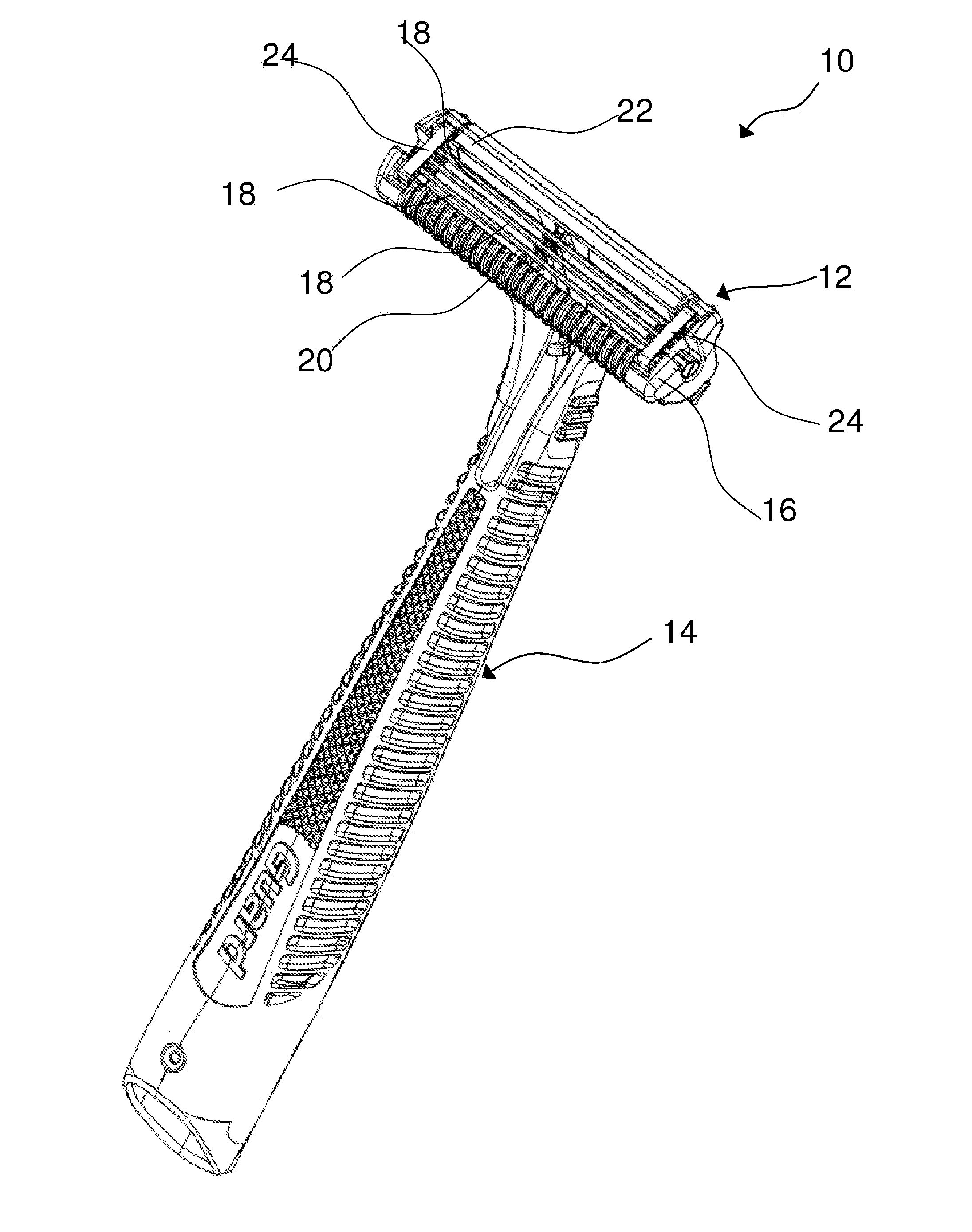
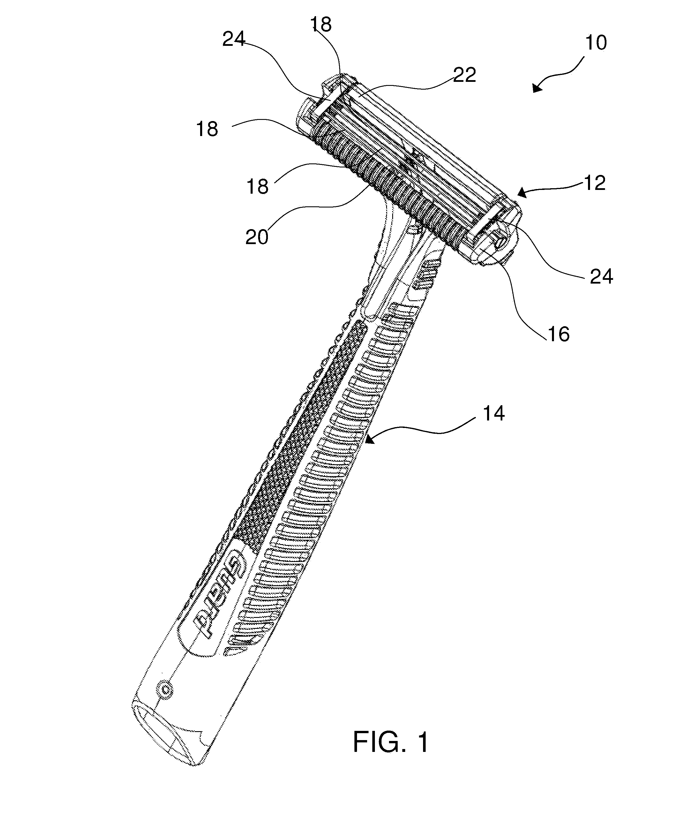
[0015]Referring to FIG. 1, one embodiment of the present disclosure is shown illustrating a shaving razor 10 having a shaving cartridge 12 mounted to a shaving razor handle 14. The shaving cartridge 12 may be pivotably (i.e., rotation of the cartridge 12 about an axis relative to the shaving razor handle 14) and / or detachably engaged to the shaving razor handle 14. The shaving cartridge 12 may include a housing 16 dimensioned to receive at least one bent blade 18. Although three blades 18 are shown, the housing 16 may have more or fewer blades 18 depending on the desired performance and cost of the shaving razor 10. The housing 16 may have a guard 20 in front of the blades 18 and a cap 22 behind the blades 18. The guard 20 and the cap 22 may aid in establishing a proper shaving geometry (e.g., blade exposure) for the shaving cartridge 12.

[0016]The blades 18 may be mounted to the housing 16 and secured in at least one direction by at least one clip 24. The blades 18 may be rigidly fi...


PUM

PropertyMeasurementUnit
roughnessaaaaaaaaaa
roughnessaaaaaaaaaa
roughnessaaaaaaaaaa

Abstract

A razor blade manufactured by the process of cutting a strip of blade steel into discrete blanks each having an elongated edge and an elongated support portion extending between a pair of lateral end faces generally transverse to the elongated edge. The elongated edges are sharpened to form a cutting edge. The discrete blanks are deformed to form a bent portion. The lateral end faces are treated to remove cracks prior to being deformed.

Description

FIELD OF THE INVENTION[0001]The present invention relates to razor cartridges and blades in general and, more particularly, to razor blade cartridges having one or more razor blades with a bent portion and a method for manufacturing the same.BACKGROUND OF THE INVENTION[0002]Razor blades are typically formed of a suitable metallic sheet material such as stainless steel, which is slit to a desired width and heat-treated to harden the metal. The hardening operation utilizes a high temperature furnace, where the metal may be exposed to temperatures greater than 1145° C., followed by quenching. After hardening, a cutting edge is formed on an elongated edge of the blade. The cutting edge typically has a wedge-shaped configuration with an ultimate tip having a radius less than about 1000 angstroms, e.g., about 200-300 angstroms.[0003]The razor blades are generally mounted on a plastic housing (e.g., a cartridge for a shaving razor) or on a bent metal support that is attached to a housing. ...

Claims


Application Information

Patent Timeline
Patent Type & Authority Applications(United States)
IPC IPC(8): B26B21/14B21K11/00
CPCB21D11/10B21D19/005B26B21/565B23P15/403B26B21/4068B21D53/645
Inventor PETERSON, MARK
Owner THE GILLETTE CO
Learn More