Machining mechanical parts with a hollow cylindrical tool

a hollow cylindrical and mechanical part technology, applied in the direction of turning apparatus, maintenance and safety accessories, large fixed members, etc., can solve relatively fine dust, and inability to overcome in satisfactory manner the problems of high frequency noise and high frequency noise of milling robots, so as to avoid generating high frequency noise or generating particularly adhesive machining dust

Active Publication Date: 2006-12-28
ROMER INC
View PDF9 Cites 78 Cited by
  • Summary
  • Abstract
  • Description
  • Claims
  • Application Information

AI Technical Summary

Benefits of technology

[0014] The present invention seeks to devise a machining device making it easy to make three-dimensional mechanical parts while avoiding the above-mentioned drawbacks, and in particular avoiding generating high frequency noise or generating particularly adhesive machining dust.

Problems solved by technology

Unfortunately, such milling robots present two major drawbacks, that have not been overcome in satisfactory manner.
The first drawback is that of noise, the high speed of the spinning cutter leading to very high frequency noise and whistling that are particularly burdensome for nearby personnel, even though they generally wear helmets with sound protection, thereby de facto excluding the presence on site of other people, because of the discomfort caused.
The second drawback lies in generating relatively fine dust as a result of the milling passes, and removing such dust leads to practical problems inherent both to the size of the particles, and also to the electrostatic charge of said particles which stick to a greater or lesser extent to the surrounding equipment, and in particular to the hinged arm of the milling robot.
The dust is thus difficult to remove, and in particular, it is not possible to conceive making use of the suction techniques that are traditionally to be found in installations for removing wood sawdust, using suction that is necessarily applied laterally because of the presence of the outlet shaft of the drive motor on the axis of the tool.
Finally, in addition to the two major drawbacks mentioned above, it should also be observed that the machining device fitted to the milling robot uses a drive motor that is adapted to the speed conditions required, and consequently constitutes a component that is both expensive and fragile.
Finally, such motor drive also implies that the installation consumes a non-negligible amount of electrical power.

Method used


Image

  • Machining mechanical parts with a hollow cylindrical tool
  • Machining mechanical parts with a hollow cylindrical tool
  • Machining mechanical parts with a hollow cylindrical tool

Examples


Embodiment Construction

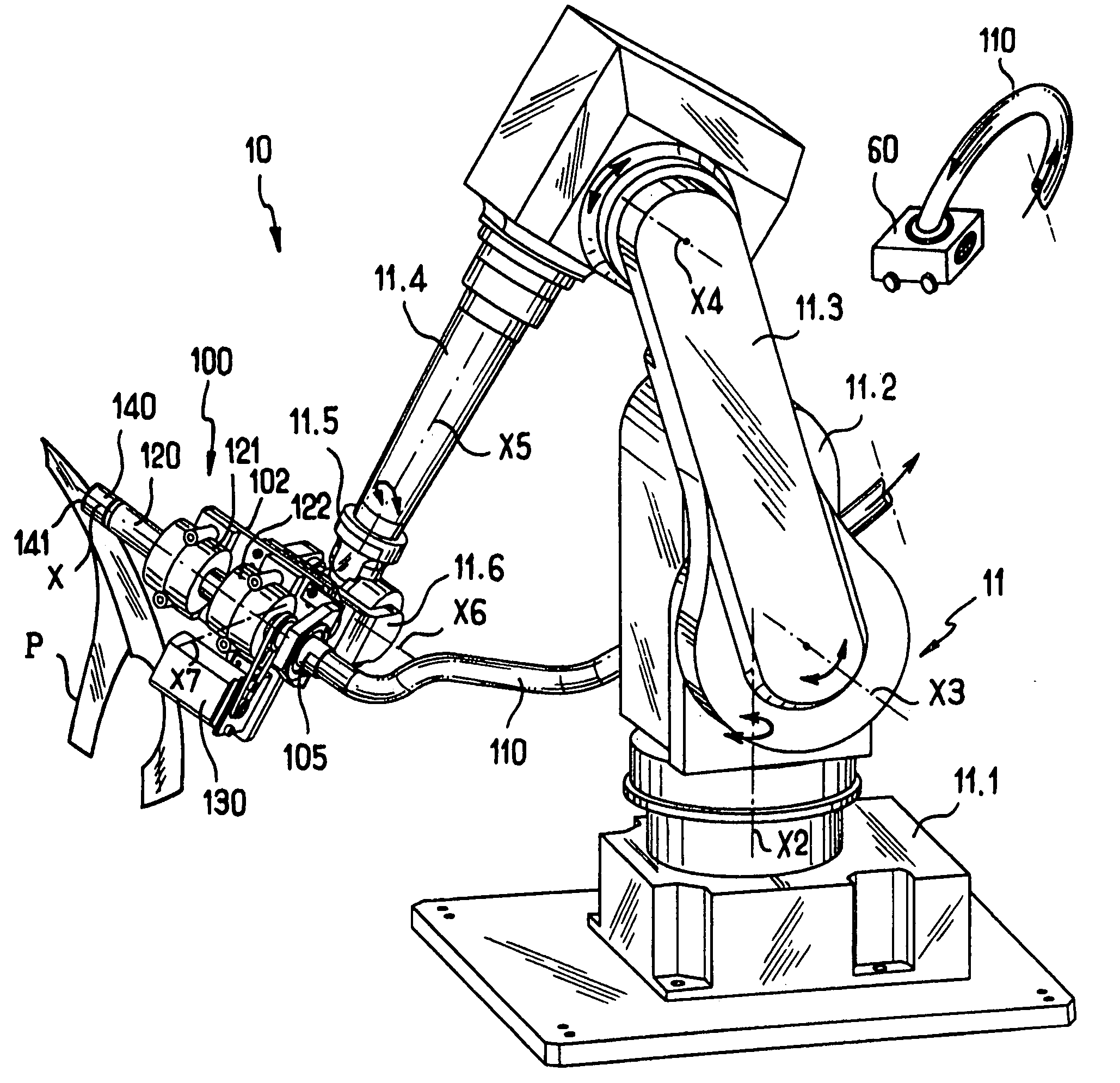
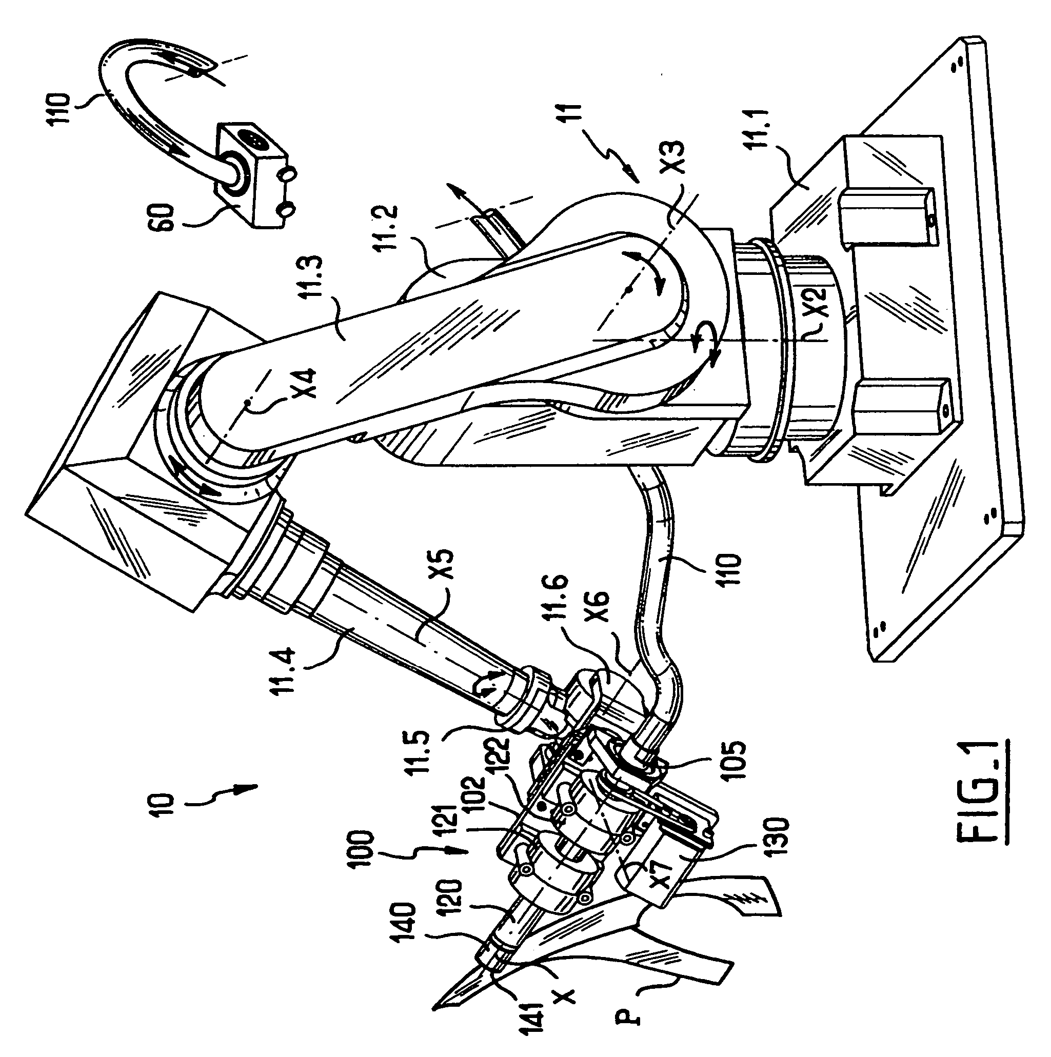
[0036]FIG. 1 shows a machining device in accordance with the reference given overall reference 100 that is for use in machining three-dimensional mechanical parts, in particular a part referenced P which in this example is a three-dimensional model of motor vehicle bodywork (specifically a front left fender), the part being machined from a solid piece of polystyrene. The field of application mentioned specifically is that of car design, however that is naturally only an example, it being understood that the invention can be applied to any type of machining of mechanical parts by means of a rotary hollow cylindrical tool.

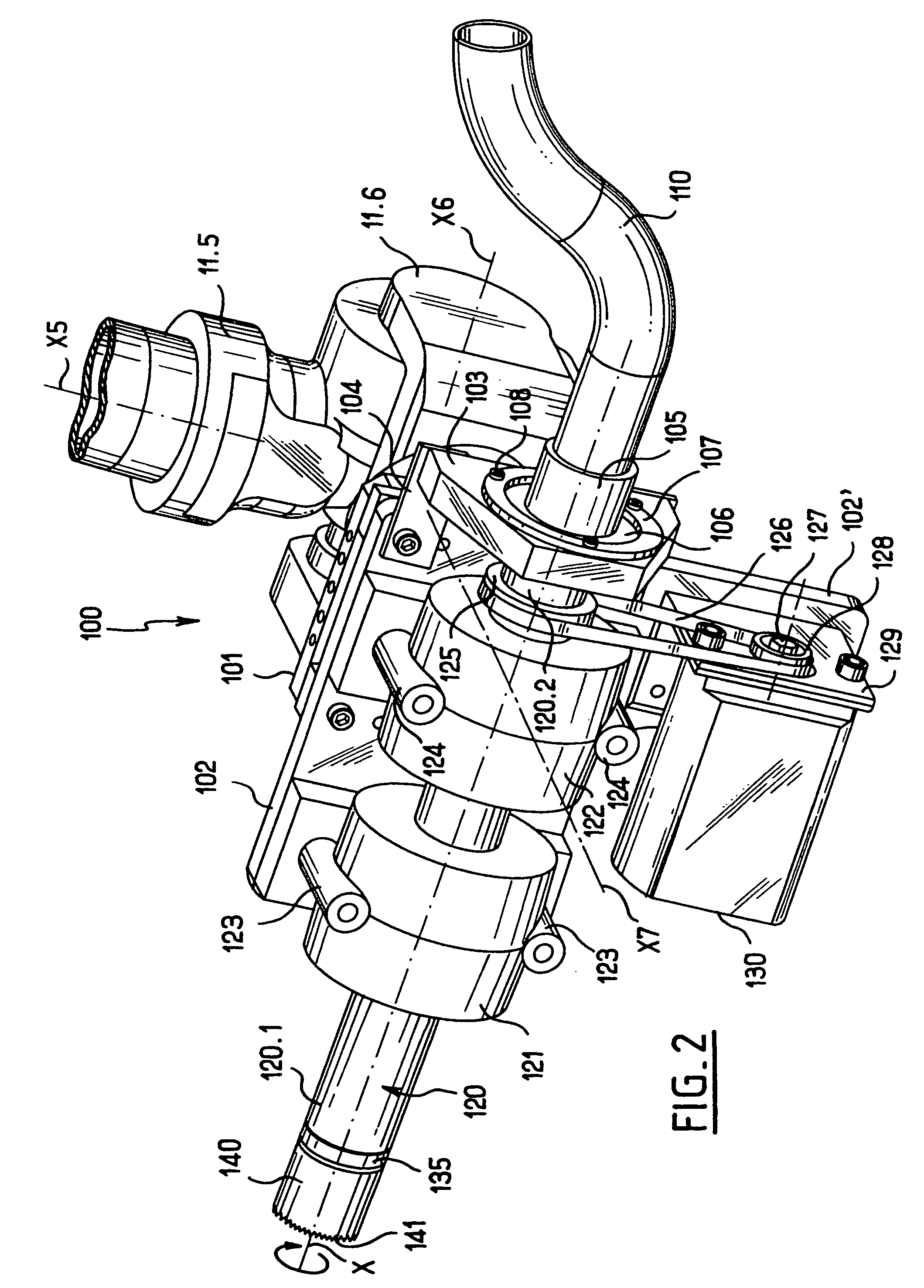
[0037] The machining device 100 in this example is mounted via a pair of plates 101 and 102 to one end of a hinged arm 11 forming part of a numerically controlled machining robot 10.

[0038] The hinged arm machining robot has a base 11.1 surmounted by a turret 11.2 capable of turning about an axis X2 that is substantially vertical, which turret is fitted on one side ...


PUM

PropertyMeasurementUnit
diameteraaaaaaaaaa
shapeaaaaaaaaaa
speedaaaaaaaaaa

Abstract

The present invention relates to a device for machining mechanical parts by means of a hollow cylindrical tool presenting a distal end with a free edge that is shaped to perform machining when said tool is rotated about its axis. In accordance with the invention, the hollow cylindrical tool is fitted internally with a transverse member forming a shaving-breaker, and said hollow cylindrical tool is secured axially to a distal end of a hollow cylindrical spindle, said hollow cylindrical spindle being mounted to rotate about its own axis on a support plate, and being driven externally by rotary drive means mounted on said support plate, and said hollow cylindrical spindle having a proximal end facing and directly adjacent to a hollow cylindrical endpiece secured to said support plate and connected to a suction hose, such that the machining shavings can be evacuated internally by passing successively through the hollow cylindrical tool going round the transverse member forming a shaving-breaker, through the hollow cylindrical spindle, through the hollow cylindrical endpiece, and through the suction hose.

Description

CROSS REFERENCE TO RELATED APPLICATIONS [0001] Applicant hereby claims foreign priority benefits under U.S.C. § 119 from French Patent Application No. 05 06543 filed on Jun. 28, 2005, the contents of which are incorporated by reference herein. FIELD OF THE INVENTION [0002] The present invention relates to the field of machining mechanical parts by means of a hollow cylindrical tool presenting a distal end with a free edge that is shaped to implement a machining operation when said tool is rotated about its axis. BACKGROUND OF THE INVENTION [0003] It has been known for a very long time to machine mechanical parts by using a hollow cylindrical tool presenting a distal end with a free edge that is shaped to implement machining when said tool is driven in rotation about its axis, the free edge generally being shaped to carry a set of teeth for attacking the material of the mechanical part that is to be machined. [0004] In the field of portable drills, proposals have already been made to...

Claims


Application Information

Patent Timeline
Patent Type & Authority Applications(United States)
IPC IPC(8): B23C1/12
CPCB23B51/0413B23B2228/28B23Q11/0046Y10T408/50Y10T409/304088Y10T408/453Y10T409/308512Y10T409/307672Y10T83/207
Inventor GRANGER, ROMAIN
Owner ROMER INC
Why Eureka
Try Eureka