High-pressure pump

Active Publication Date: 2011-12-29
ROBERT BOSCH GMBH
View PDF4 Cites 1 Cited by
  • Summary
  • Abstract
  • Description
  • Claims
  • Application Information

AI Technical Summary

Benefits of technology

[0008]According to the invention, a high-pressure pump for a fuel injection system of an internal combustion engine, in particular for a common rail injection system, is provided, which high-pressure pump has a drive shaft mounted by at least one bearing arranged in a bearing return, with at least one valve being arranged downstream of the at least one bearing, which valve has an opening pressure which lies in a range from 0.1 bar to 0.8 bar. With the high-pressure pump according to the invention which has the at least one valve with low opening pressure, the mass balance situation is

Problems solved by technology

Said opening pressure is so high that the check valves open only after the suction valves of the high-pressure fuel pump open, such that for example in a start-up situation, no leakage occurs through the bearings, which is however disadvantageous for said bearings.
For this reason, it is conventionally not possible for a valve to be provided at such bearin

Method used


Image

  • High-pressure pump
  • High-pressure pump
  • High-pressure pump

Examples


Example

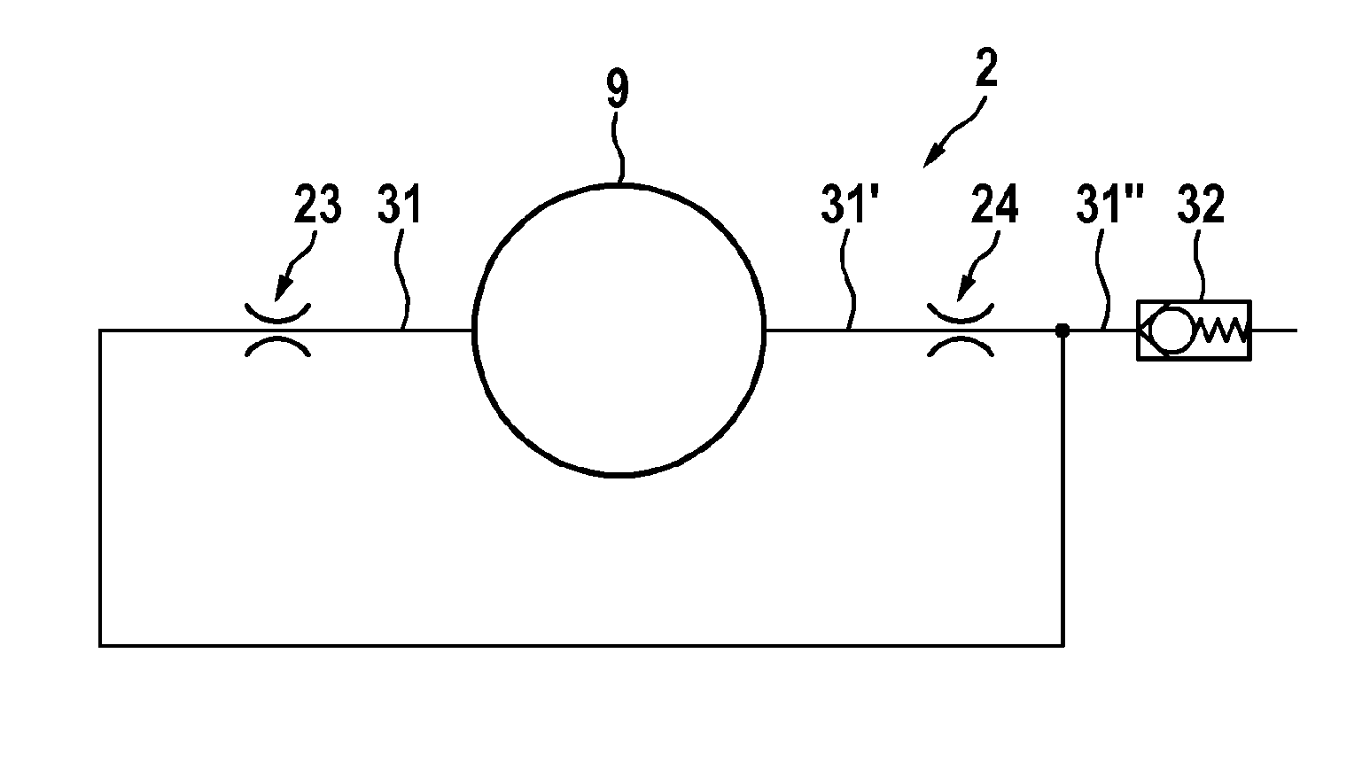
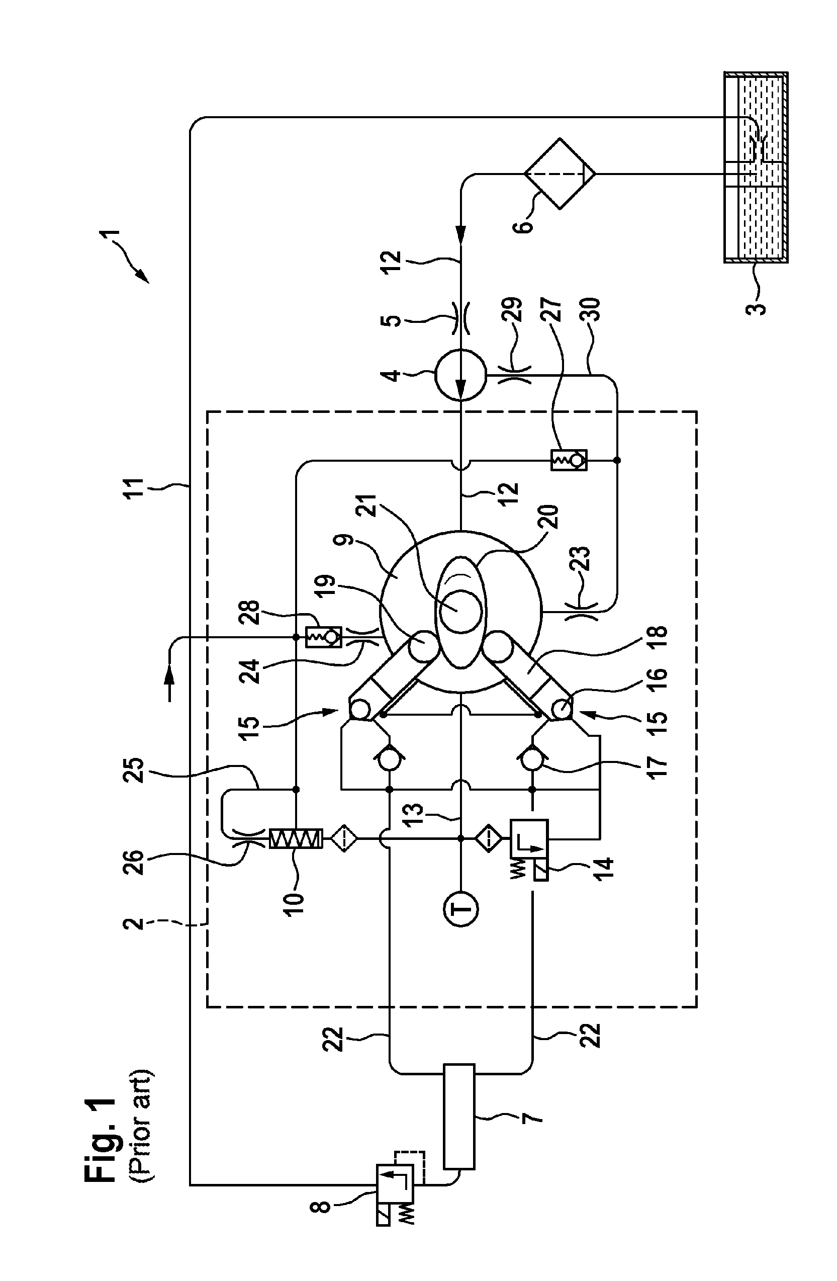
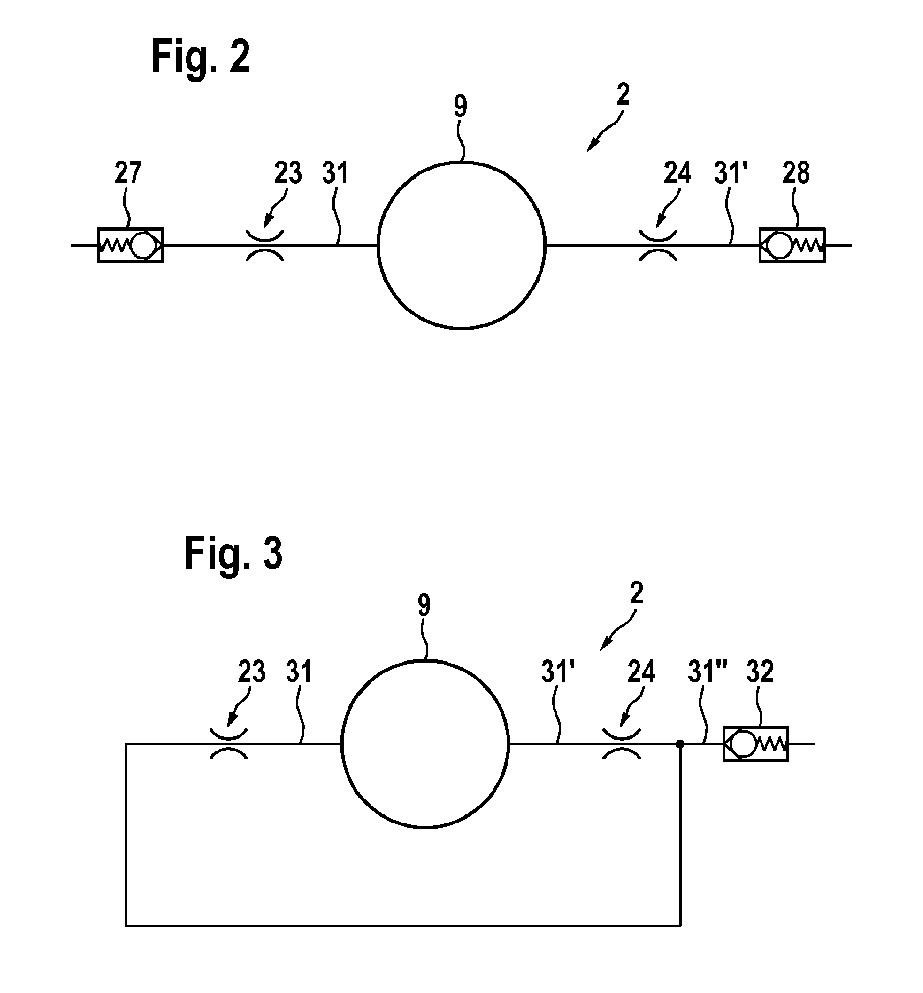
[0026]FIG. 1 illustrates a block circuit diagram of a common-rail fuel injection system 1 having a high-pressure pump 2, which system is composed substantially of a tank 3, a prefeed pump 4 with an element for feed rate limitation 5, a filter 6, a rail 7, a pressure limiting valve 8 or pressure regulating valve. The injectors which are connected to the rail 7 are not illustrated in FIG. 1.

[0027]The element for feed rate limitation 5 is designed as a throttle which is arranged directly at the inlet of the prefeed pump 4. The throttle has the effect of limiting the total fuel quantity compressed in the high-pressure pump 2. Furthermore, in this way, the resulting pressure in an interior space 9 of the high-pressure pump 2 is limited corresponding to a characteristic curve of a pressure regulating valve 10. The pressure limiting valve 8 opens into a return line 11 into which the leakage flows of the injectors (not illustrated) are also discharged. The return line 11 opens into the tank...


PUM


Abstract

The invention relates to a high-pressure pump (2) for a fuel injection system (1) of an internal combustion engine, in particular for a common-rail injection system, comprising a driveshaft (21) supported by at least one bearing (23, 24) arranged in a bearing return (31, 31′, 31″), wherein, downstream of the at least one bearing (23, 24), at least one valve (27, 28) is arranged, wherein the at least one valve (27, 28) with an opening pressure of 0.1 bar to 0.8 bar.

Description

BACKGROUND OF THE INVENTION[0001]The present invention relates to a high-pressure pump for a fuel injection system of an internal combustion engine, in particular for a common rail injection system.[0002]High-pressure pumps for example for common-rail systems are known from the prior art, in which high-pressure pumps a drive shaft is mounted by means of plain bearings which are supplied with pressure and which serve to provide optimum lubrication and cooling. Furthermore, valves which are arranged in series with the bearings in a hydraulic circuit may be arranged downstream of the bearings in order to prevent the flows through the bearings upon start-up.[0003]For example, DE 10 2006 048 356 A1 discloses a high-pressure fuel pump for an internal combustion engine, in which fuel inevitably flows through the bearings of the drive shaft, and as a result the mechanical and thermal load capacity of the bearings and therefore of the entire high-pressure fuel pump is considerably increased....

Claims


Application Information

Patent Timeline
IPC IPC(8): F02M69/46F02M69/04
CPCF02M59/06F02M63/0001F04B53/1002F02M63/0225F04B1/0452F02M63/005
Inventor LANGENBACH, CHRISTIAN
Owner ROBERT BOSCH GMBH
Why Eureka
Try Eureka