Grinding machine

a grinding machine and eccentric drive technology, applied in the direction of grinding machine components, grinding/polishing apparatus, grinding machines, etc., can solve the problems of affecting the grinding effect, imbalance cannot be completely balanced, and the grinding machine is caused to vibrate strongly, etc., to achieve good grinding effect and low complexity

Inactive Publication Date: 2013-07-02
HANS WEBER MASCHFAB
View PDF9 Cites 1 Cited by
  • Summary
  • Abstract
  • Description
  • Claims
  • Application Information

AI Technical Summary

Benefits of technology

[0005]It is an object of the present invention to disclose a grinding machine of the kind mentioned in the introduction which makes it possible to obtain a good grinding result with low complexity and which avoids the disadvantages mentioned above.
[0007]The solution according to the invention makes it possible to produce overlapping non-linear grinding marks with a single eccentric drive. In the most simple case the grinding bar contains two grinding shoes of equal mass wherein the eccentricities of the eccentrics assigned to the two grinding shoes are equal but displaced from one another by 180° relative to the drive axis. This arrangement guarantees a perfect mass balance. Each grinding shoe functions as a counter mass for the respective other grinding shoe so that the occurrence of vibrations due to unbalanced masses is prevented. At the same time the movement of the two grinding shoes in opposite directions causes the grinding marks produced by the abrasive grains of the two grinding shoes to overlap each other in a complex manner on the work piece surface whereby a high-quality grinding result is achieved.
[0008]According to an alternative embodiment the grinding bar has three grinding shoes of equal mass wherein the two outer ones are rigidly connected to each other for common movement and the eccentricity of the eccentrics assigned to the middle grinding shoe is twice as big as the eccentricities of the eccentrics assigned to the outer grinding shoes and displaced by 180° with regard to them. This solution provides for a complete mass balance and at the same time renders an even more complex overlapping of the grinding marks. A major advantage of the solution according to the invention is that such a grinding result is achieved with a single eccentric drive.

Problems solved by technology

The overlapping eccentric drives entail a considerable complexity of the construction.
Moreover there is a problem in that great overhung masses are put into a fast circular motion eccentrically and the resulting imbalance cannot be completely balanced out even with the use of counter weights.
Thus the grinding machine is caused to vibrate strongly during operation.
These solutions also require very complex constructions.

Method used


Image

  • Grinding machine
  • Grinding machine
  • Grinding machine

Examples


Embodiment Construction

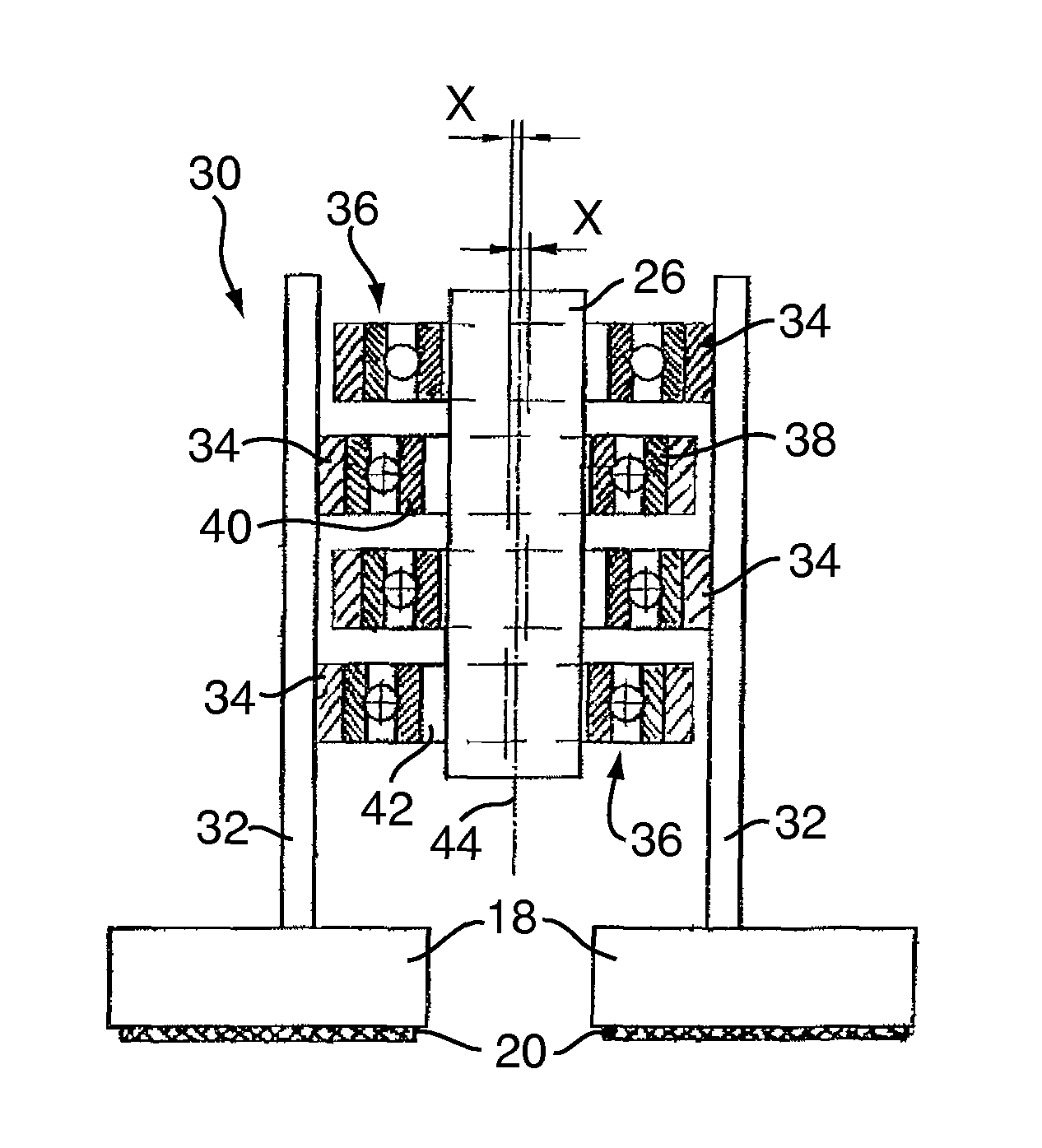
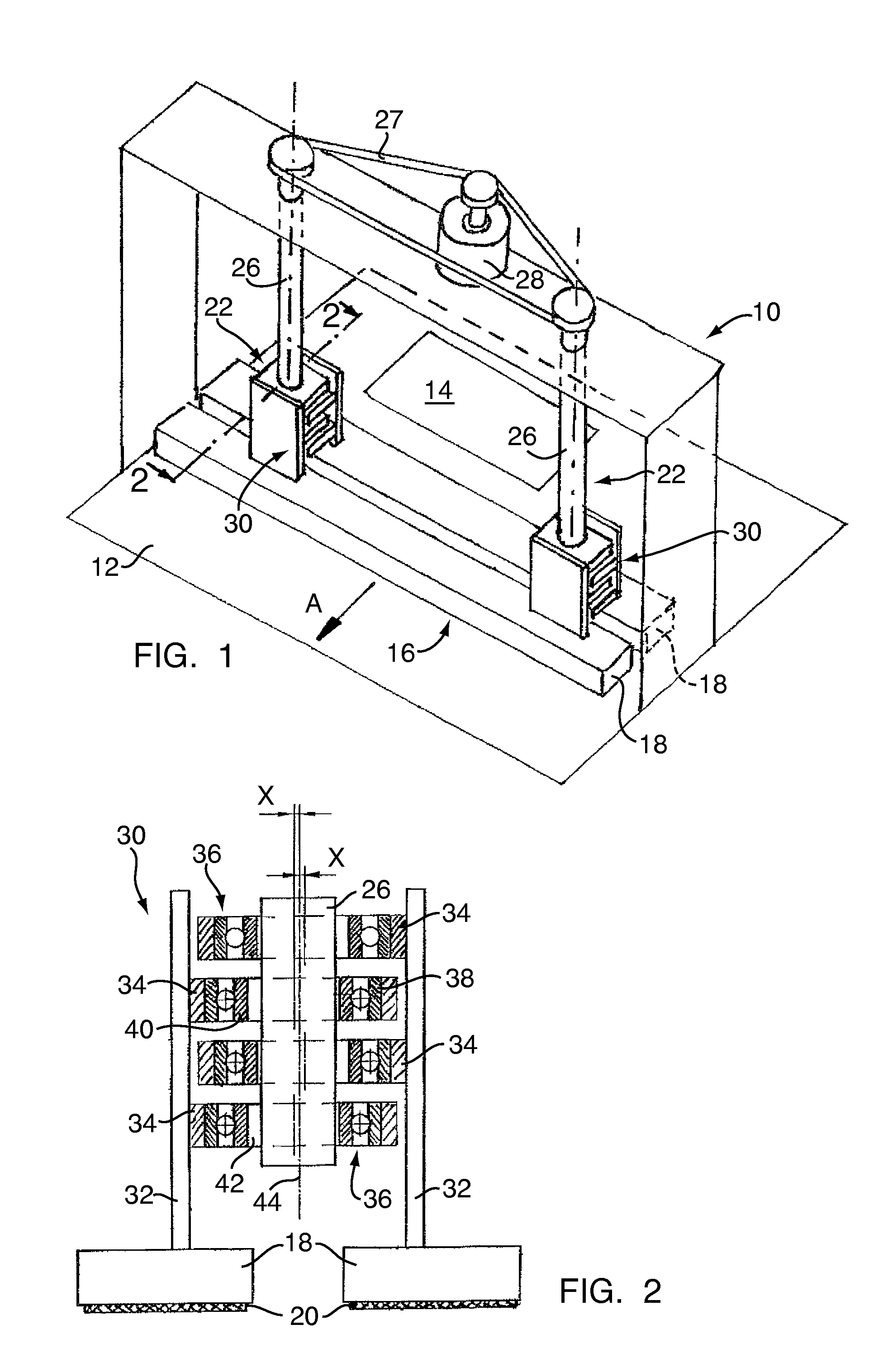
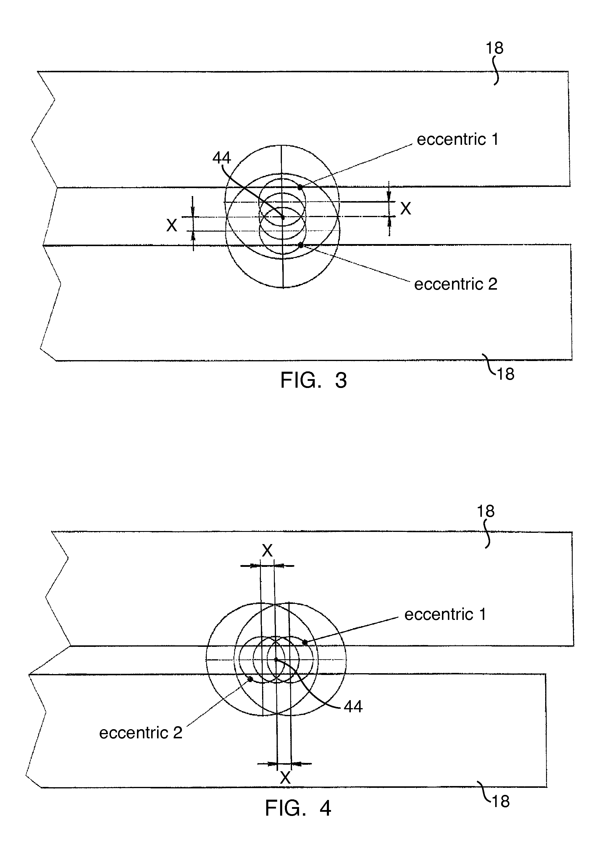
[0014]The grinding machine depicted schematically in FIG. 1 contains a machine frame generally denoted at 10 with a work piece support surface 12 on which a work piece 14 can be transported through the machine in the direction of the arrow A, which transport is as a rule carried out with the help of a transport arrangement not depicted in the drawing. A grinding bar arrangement 16 containing two grinding shoes 18 positioned in parallel is arranged transversely with respect to the work piece feeding direction A across the width of the work piece support surface. The two grinding shoes 18 carry a grinding medium 20 (FIG. 2) on their lower surfaces, i.e. on the surfaces facing the work piece support surface 12, and are suspended via a eccentric drive generally denoted at 22 from a portal 24 of the machine frame 10 which portal spans the work piece support surface 12. The eccentric drive 22 contains two drive shafts or eccentric shafts 26 which are driven via a belt 27 or a chain by a m...


PUM


Abstract

A grinding machine includes a machine frame with a work piece support surface on which a work piece may be transporter through the machine. A grinding bar arrangement including two grinding shoes positioned in parallel is arranged transversely with respect to a work piece feeding direction across the width of the work piece support surface. The two grinding shoes carry a grinding medium on their surfaces facing the work piece support surface and are suspended via an eccentric drive. The two grinding shoes perform rotary movements in a plane parallel to the work piece support surface achieving a high quality grinding result.

Description

CROSS REFERENCE TO RELATED APPLICATIONS[0001]Applicants hereby claim foreign priority benefits under 35 U.S.C. §119 of German Patent Application No. 10 2010 016 606.5 filed Apr. 23, 2010, the disclosures of which are herein incorporated by reference.BACKGROUND OF THE INVENTION[0002]The invention concerns a grinding machine containing a machine frame having a work piece support surface and at least one grinding bar moveably mounted on the machine frame and extending transversely across the work piece support surface which grinding bar carries a grinding medium on its surface facing the work piece support surface and which grinding bar can be driven by means of an eccentric drive in a circular movement parallel to the work piece support surface in such a way that it travels in circles parallel to itself, the eccentric drive having at least two eccentric shafts which are directed perpendicularly to the work piece support surface and which are distanced from each other in the longitudin...

Claims


Application Information

Patent Timeline
Patent Type & Authority Patents(United States)
IPC IPC(8): B24B7/00
CPCB24B7/005B24B41/042
Inventor WEBER, MARKUSENGELHARDT, CHRISTIAN
Owner HANS WEBER MASCHFAB
Why Eureka
Try Eureka