Roller Skate steering and suspension mechanism

a technology of suspension mechanism and roller skate, which is applied in the direction of snowboard binding, skates, agriculture tools and machines, etc., can solve the problems of shortening the wheelbase, mechanical instability, and becoming stiff and unresponsive when tightened sufficiently, so as to improve the performance and robustness of both steering and suspension, the effect of reducing the structural strength

Active Publication Date: 2011-12-29
BURKE JACOB
View PDF5 Cites 21 Cited by
  • Summary
  • Abstract
  • Description
  • Claims
  • Application Information

AI Technical Summary

Benefits of technology

[0019]According to another aspect of the present invention, the pivot pin is axially adjustable to regulate force of contact between the pivot and the pivot cup, thereby providing mechanical preloading for the roller skate steering and suspension mechanism against both static and dynamic loads.
[0020]According to yet another aspect of the present invention, the base plate is made of a single piece of material and includes a transversely open reinforcing arch to provide lightweight lengthwise stiffening, wherein the transverse opening through the arch is an oval and the area underneath the arch is open through the body of the base plate, thus providing further lightening of the base plate with a minimum of decrease in structural strength.OBJECTS AND FEATURES OF THE INVENTION
[0021]It is an object of the present invention to provide a roller skate steering and suspension mechanism with a triple action to improve the performance and robustness of both steering and suspension under both static and dynamic loads.
[0022]It is another object of the present invention to provide a lighter, stiffer and more durable base plate as part of the roller skate steering and suspension mechanism.

Problems solved by technology

Skate trucks generally sacrifice the ability to turn in exchange for lateral stability, thus becoming stiff and unresponsive when tightened sufficiently.
Conversely, loosening the trucks for improved turning can lead to mechanical instability.
This geometry also tends to shorten the wheelbase, thus further decreasing overall stability.
It has been found that having an approximately 45 degree angle between the pivot pin and the base plate, and also an approximately 45 degree angle between the kingpin and the base plate, yields a very responsive steering geometry, though with a consequent decrease in lateral stability.
For competitive roller skating activities such as roller derby, the skate mechanism is subjected to extreme impacts during jumps and falls, as well as the stresses of high speed skating, tight turns and the dynamic forces caused by sudden acceleration and deceleration.
One particular problem with prior art skate mechanisms is wear and damage to the pivotal connection between the truck and the base plate.
This will wear the joint and over time the amount of separation and slap will increase.
The skate mechanism will also feel looser and less tightly controlled, and may eventually fail due to stress and impact.
Additionally, slap and mechanism play will cause fatigue to the skater and may even promote joint injuries.
Mechanism play can also increase the probability of sudden component failure.
The impacts experienced by the skate mechanisms can cause the cushions to suffer heavy uneven wear, the pivot cups to wear and even crack, and the kingpins to crack as well.
Sudden component failure can easily lead to skater injuries.
Also, increasing steering responsiveness by overly loosening the resilient clamping around the trucks can lead to sudden pivot joint separation and consequent spinning of the truck around the kingpin, with skater injury being a likely result.
This cup will wear over time and under extreme circumstances (which are not infrequently encountered in activities such as roller derby) may actually crack apart.
Eventually it will wear and then slap will increase.
However, the '762 patent does not teach any means for preloading the pivot mechanism for protection against static and dynamic forces, and the resilient cup provides a very limited amount of shock absorbing and historically has been prone to high wear and even splitting apart.
However, the pivot pin taught by the '262 patent primarily offers free rotation around a single axis rather than in all directions as a ball joint provides, and suffers the well known problems of the limited shock absorbing response and limited durability provided by a resilient cup.
Nor is the pivot pin adjustable for preloading.
However, the '987 patent also suffers from the problems of the limited shock absorbing response and limited durability provided by a resilient cup, even though the ball joint will provide an improvement in rotation.

Method used


Image

  • Roller Skate steering and suspension mechanism
  • Roller Skate steering and suspension mechanism
  • Roller Skate steering and suspension mechanism

Examples


Embodiment Construction

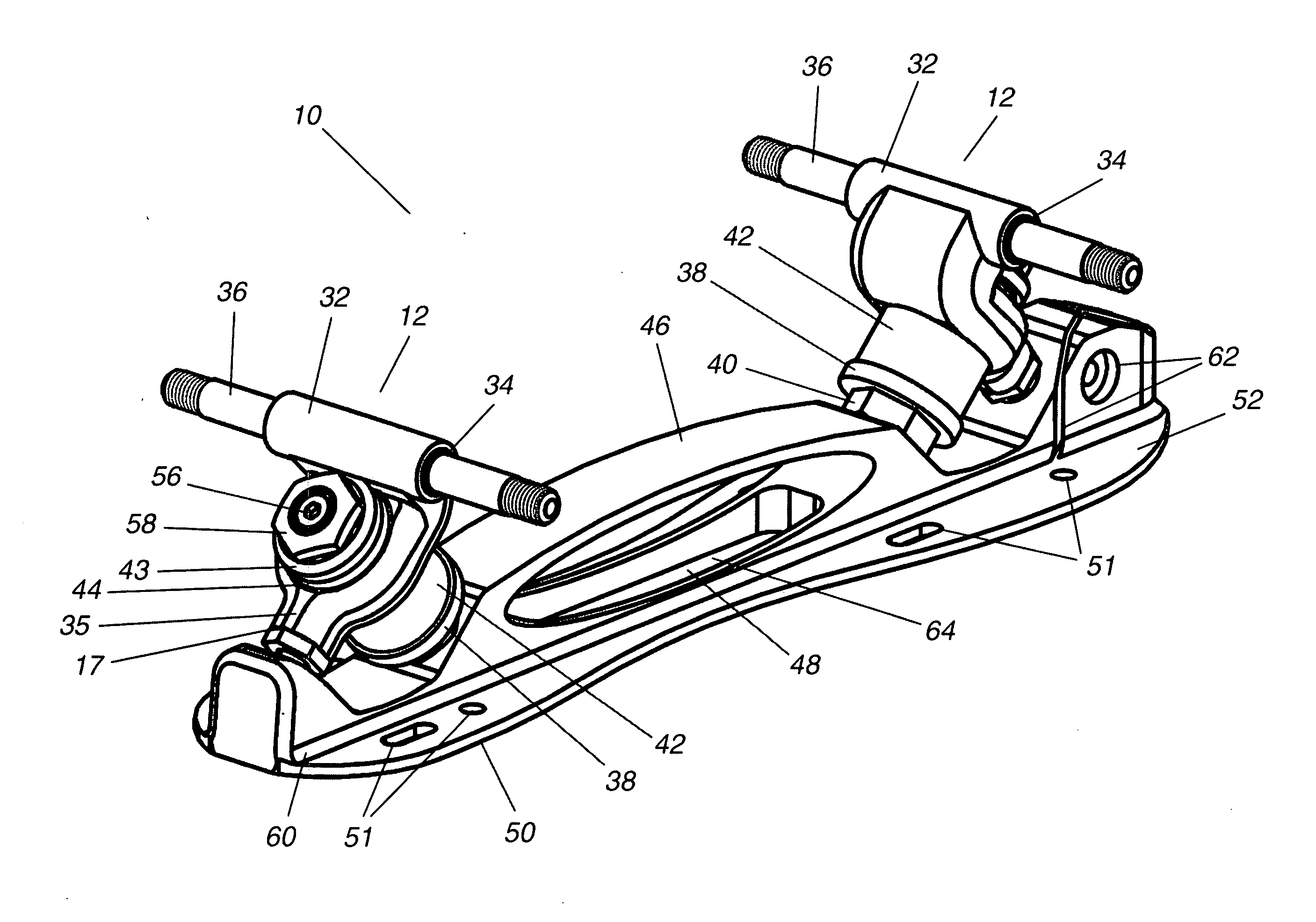
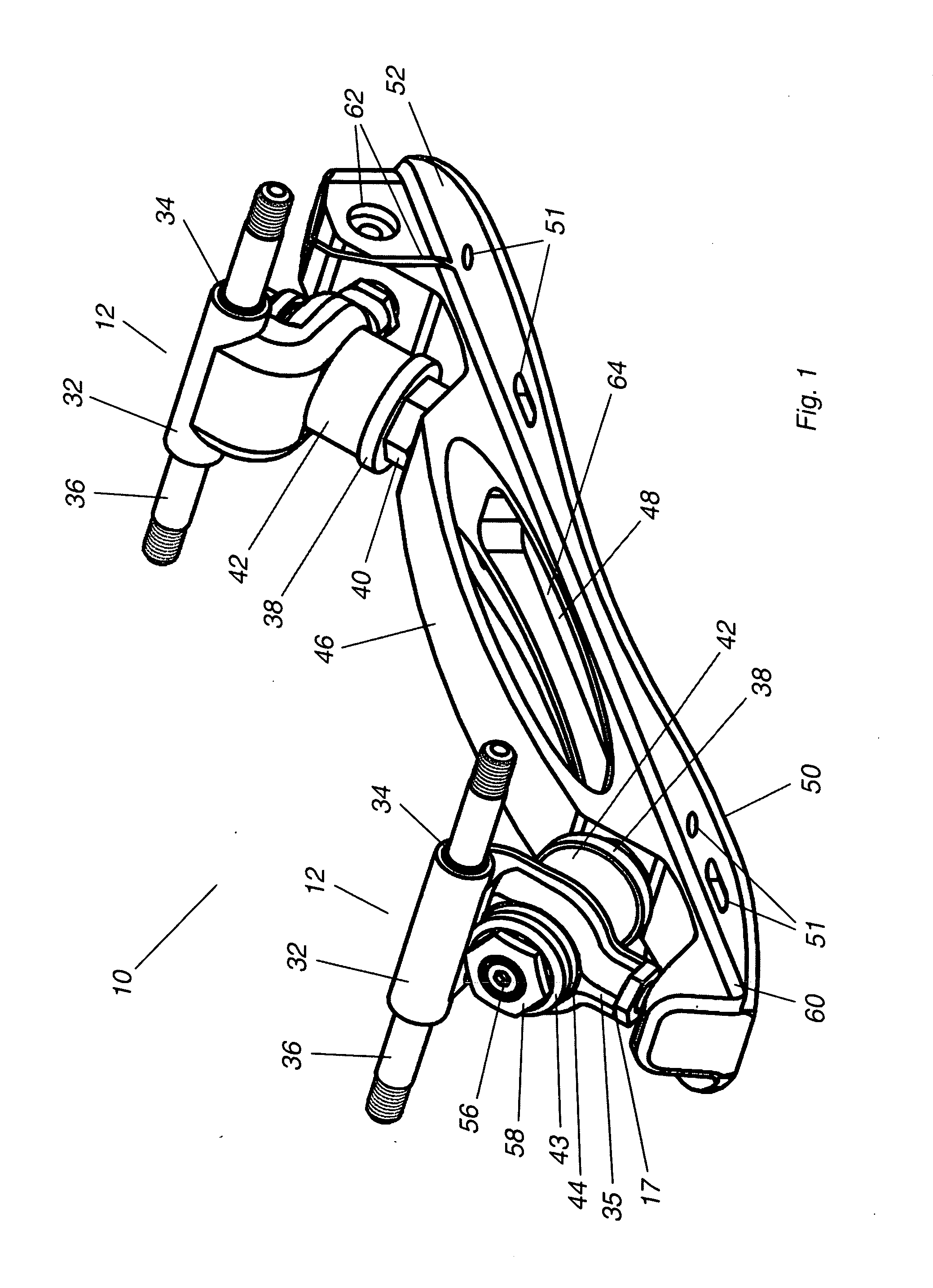
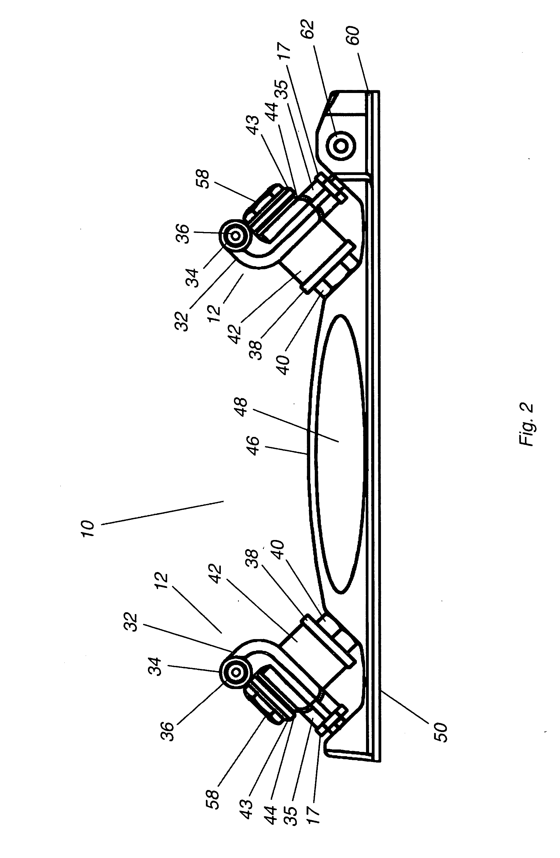
[0043]FIG. 1 shows a first version of the roller skate steering and suspension mechanism 10. A skate truck assembly 12 is mounted at each end of the base plate 50 by means of a kingpin 40 upon which are sequentially placed an inner cushion support 38, an inner cushion 42, a skate truck 32, an outer cushion 44, an outer cap 43, a micrometer nut 58 and a kingpin set screw 56. The inner cushion 42 and outer cushion 44 are clamped against the skate truck 32 and the micrometer nut 58 is used to set the degree of clamping pressure with fine control. The micrometer nut 58 is locked in place by the kingpin set screw 56. This portion of the mechanism provides a means for double action steering and suspension and is shown both as an assembly and in an exploded form in FIG. 3. Preferably the inner cushion 42 and the outer cushion 44 are made of a elastomeric materials such as urethane. Identical or different resilient materials can be used to additionally tune the steering and suspension respo...


PUM


Abstract

A triple action roller skate steering and suspension mechanism includes upper and lower cushions clamped on either side of a skate truck, plus a third action comprising a floating cushion mechanism supporting and surrounding the pivot cup portion of a pivot joint mechanism. A pivot pin is threaded into the skate truck and can be preloaded against the pivot cup and floating cushion mechanism, thereby providing improved shock absorbing, durability and adjustability. The roller skate base plate is a unitary structure including a hollow arch for lightweight structural reinforcement.

Description

[0001]This patent application claims the benefit of the priority date of Provisional Patent Application No. 61 / 398,371 filed Jun. 24, 2010 entitled ROLLER SKATE STEERING AND SUSPENSION MECHANISM.BACKGROUND OF THE INVENTION[0002]1. Field of the Invention[0003]The present invention relates generally to a roller skate steering and suspension mechanism, and more particularly to a triple action steering and suspension mechanism providing more responsive and durable operation during competitive roller skating.[0004]2. Description of the Prior Art[0005]Roller skate steering and suspension mechanisms have been in production for over a century. The modern quad roller skate, with a forward pair of wheels and a rear pair of wheels, generally has each pair of wheels secured to an axle which is mounted in a truck that is pivotally connected to a skate base plate, which is in turn secured to the skate boot or shoe. The trucks provide steering response whereby when a skater shifts weight laterally...

Claims


Application Information

Patent Timeline
Patent Type & Authority Applications(United States)
IPC IPC(8): A63C17/00
CPCA63C17/02A63C17/0093
Inventor BURKE, JACOB E.
Owner BURKE JACOB
Why Eureka
Try Eureka