

Time domain multiplexing for imaging using time delay and integration sensors
a time delay and integration sensor technology, applied in the field of time delay integration (tdi) sensors, can solve problems such as mixing of corresponding images
- Summary
- Abstract
- Description
- Claims
- Application Information
AI Technical Summary
Benefits of technology
Problems solved by technology
Method used
Image

Examples
Embodiment Construction
[0048]Unless specified otherwise, identical or similar reference numerals appearing in different Figures refer to identical or similar components.
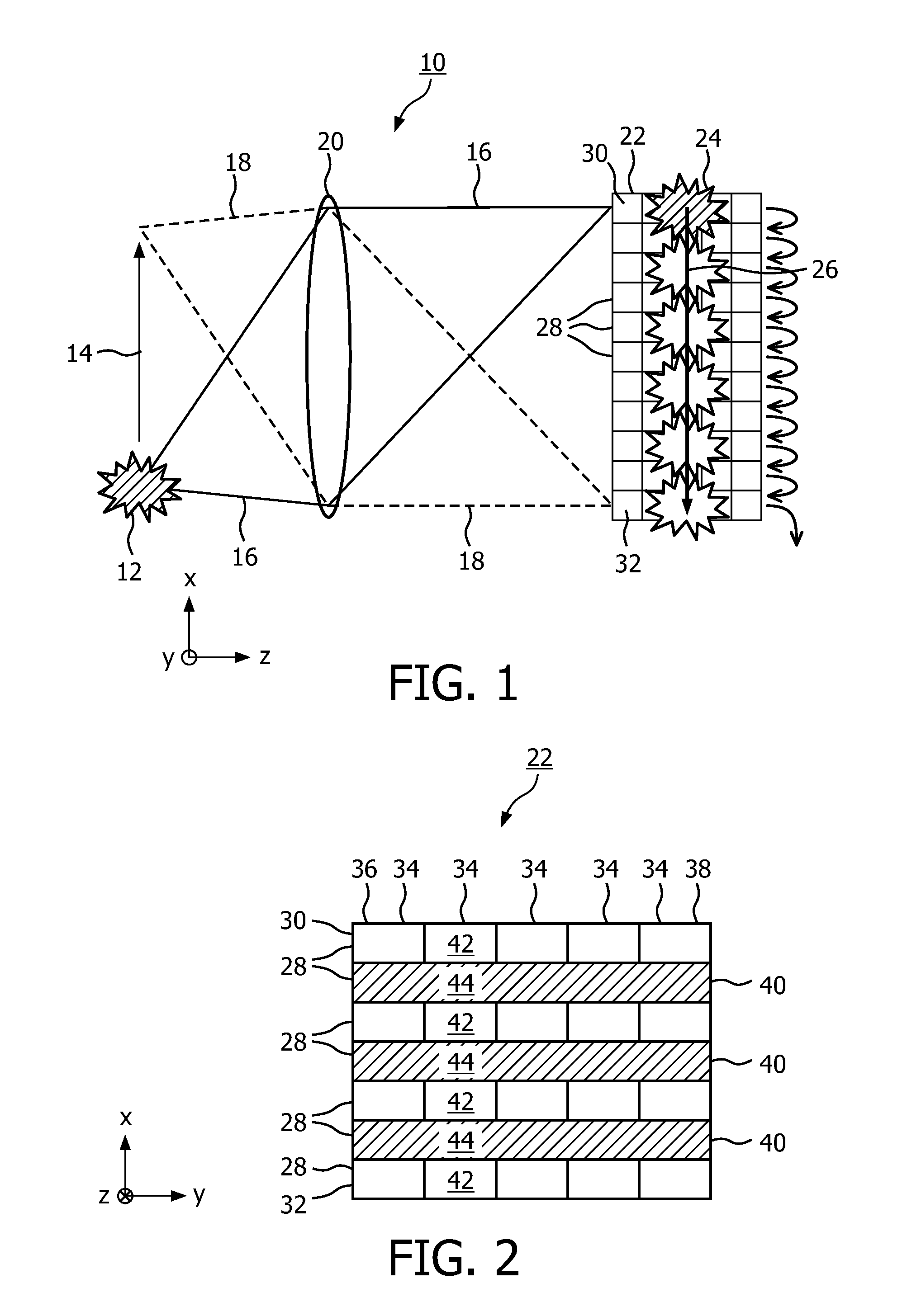
[0049]FIG. 2 schematically represents a front view of a TDI sensor 22. Each small rectangle represents an individual pixel (cell) of a CCD. The TDI sensor 22 comprises in particular a sequence of cells 42, 44, 42, 44, 42, 44, 42 numbered 1 to N. In the example shown, N=7. In practice the number of cells in the sequence is typically much larger. The sensor is configured for shifting a charge from the cell numbered 1 (the top cell 42 in the Figure, in the first row 30) via the cells numbered 2 to N-1, to the cell numbered N (the lowest cell 42 in the Figure, in the last row 32). Each cell 42, 44 is either sensitive or insensitive in the sense that when the sensor 22 is evenly illuminated by light having a first spectrum, the intensity of the light incident on any of the insensitive cells 44 is at most 10% of the intensity of the light incide...
PUM
 Abstract
Description
Claims
Application Information