Joint recognition member
a recognition member and joint technology, applied in the field of joint recognition, can solve the problems of increasing cost and increasing cost, and achieve the effect of reducing manufacturing cost and fast recognition
- Summary
- Abstract
- Description
- Claims
- Application Information
AI Technical Summary
Benefits of technology
Problems solved by technology
Method used
Image
Examples
Embodiment Construction
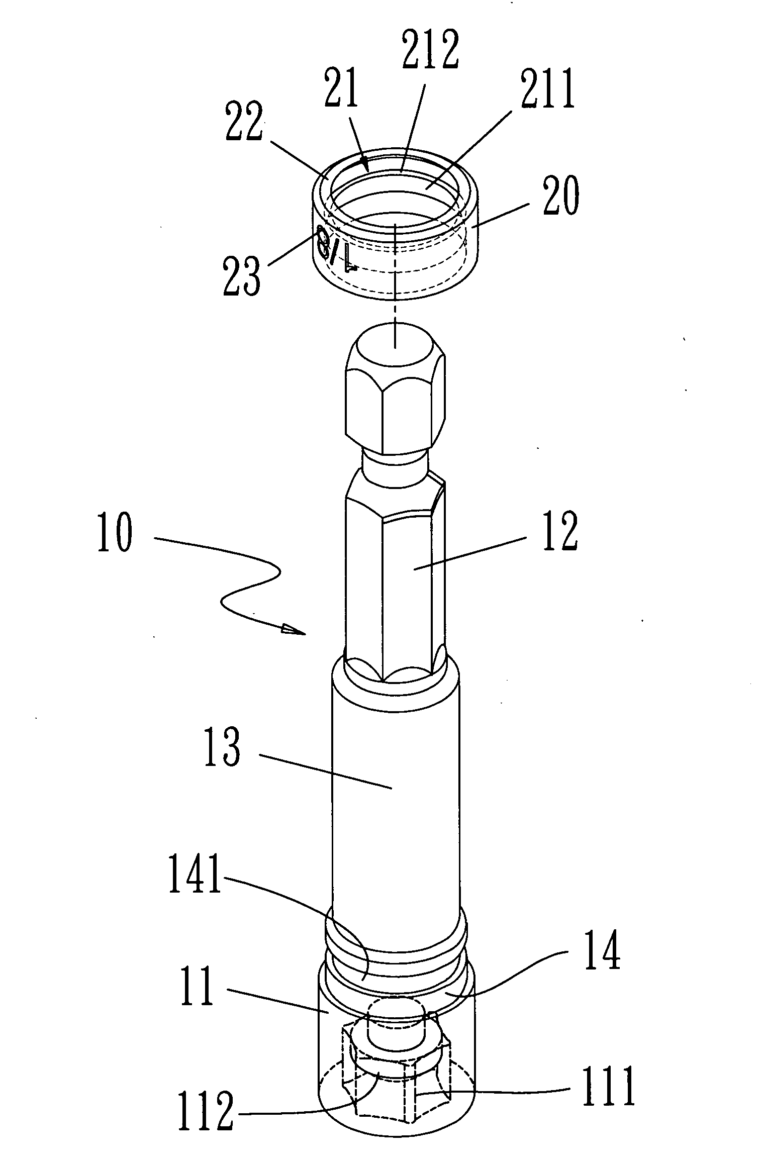
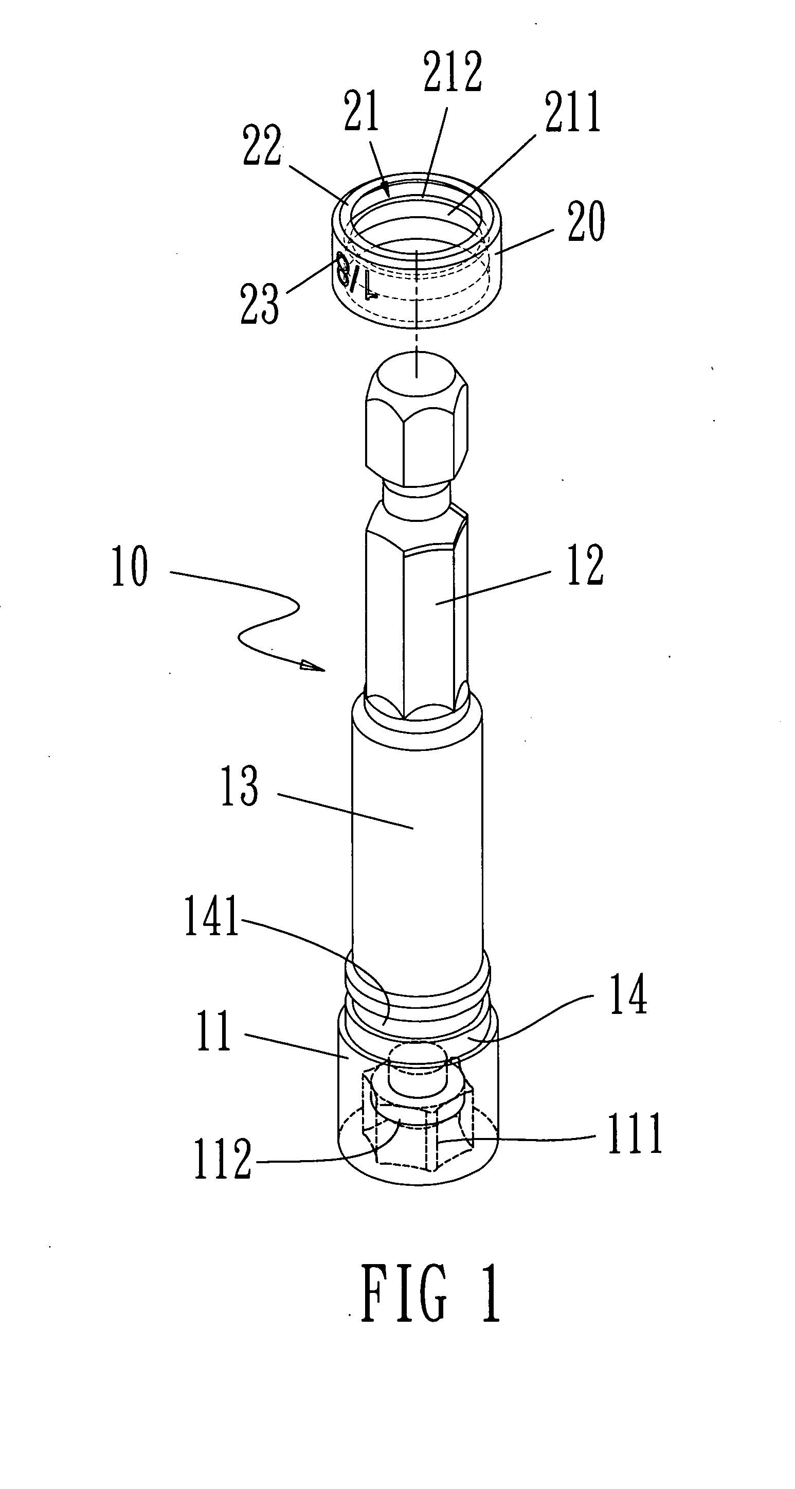
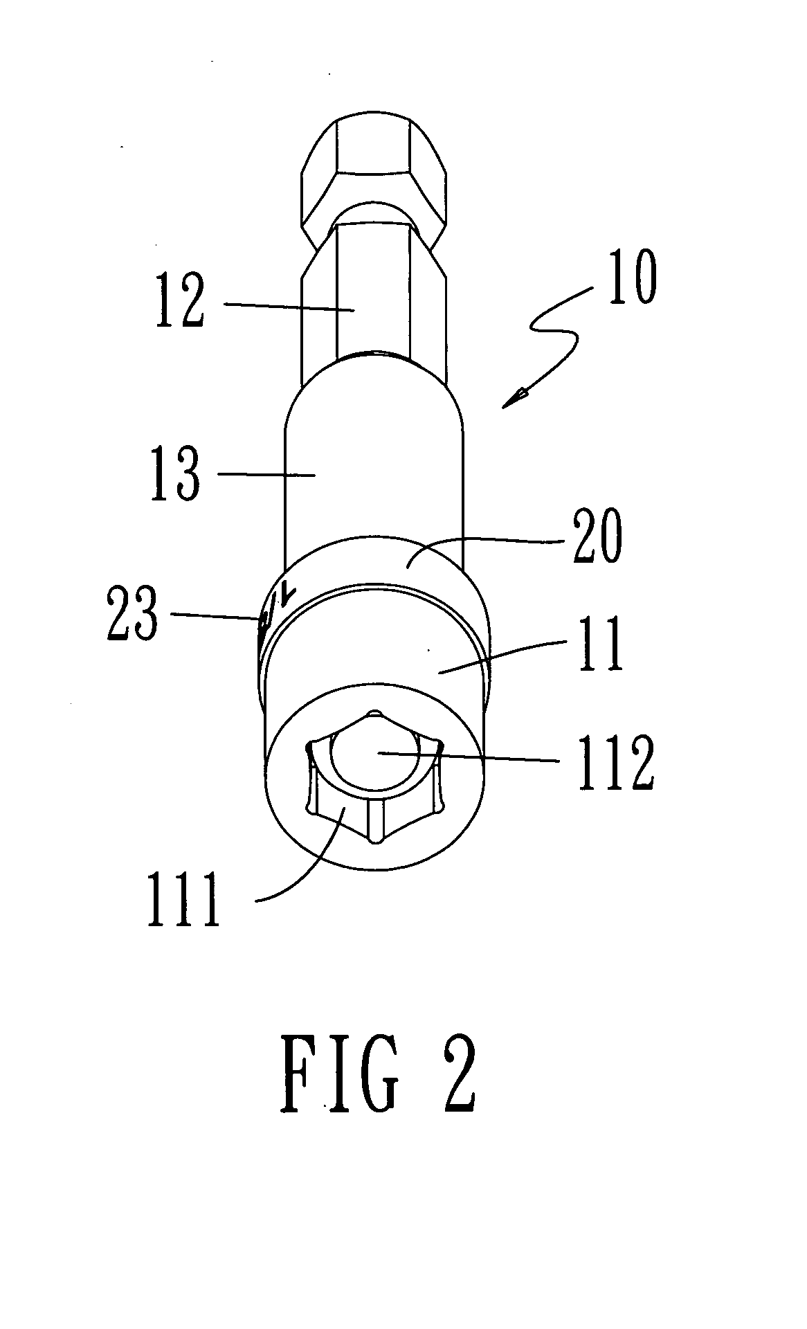
[0030]Refer from FIG. 1 to FIG. 3, an embodiment of a joint recognition member according to the present invention includes a joint body 10 and a ring 20.
[0031]The joint body 10 includes a cylinder 11 on one end and a polygonal prism 12 on the other end thereof. A middle cylinder 13 is connected between the cylinder 11 and the polygonal prism 12. A polygonal hole 111 is set on an opening end of the cylinder 11 and a magnetic part 112 is mounted on an inner end of the polygonal hole 111. Thus a driver bit (not shown in figure) is attracted by a magnetic force of the magnetic part 112 to be connected and located. The outside diameter of the cylinder 11 is larger than the diameter of the polygonal prism 12. Moreover, a narrow neck part 14 with a ring groove 141 is arranged at one end of the cylinder 11 that is near the polygonal prism 12.
[0032]The ring 20 is wrapped around the narrow neck part 14 and is having a protruding ring 21 on an inner surface thereof for being mounted, limited a...
PUM
 Abstract
Description
Claims
Application Information
 - R&D
- Intellectual Property
- Life Sciences
- Materials
- Tech Scout
- Unparalleled Data Quality
- Higher Quality Content
- 60% Fewer Hallucinations
Browse by: Latest US Patents, China's latest patents, Technical Efficacy Thesaurus, Application Domain, Technology Topic, Popular Technical Reports.
© 2025 PatSnap. All rights reserved.Legal|Privacy policy|Modern Slavery Act Transparency Statement|Sitemap|About US| Contact US: help@patsnap.com


