Apparatus and method for measuring in vivo biomechanical properties of skin

a skin and biomechanical technology, applied in the field of skin biomechanical properties measurement, can solve the problems of inability to estimate directionally dependent nt and nl values, complex mechanical behaviour of human skin, and lack of commercial devices, etc., to achieve high tolerance engagement, facilitate reattachment, and improve the degree of stability

Inactive Publication Date: 2011-12-29
NAT UNIV OF SINGAPORE
View PDF0 Cites 11 Cited by
  • Summary
  • Abstract
  • Description
  • Claims
  • Application Information

AI Technical Summary

Benefits of technology

[0013]The present invention may avoid the invasive approach of surgery, in order to obtain the mechanical properties of the skin, by taking an alternative non-invasive approach, through mere attachment of the measurement device to the skin. Whilst a surgical approach may provide additional information, it is unnecessary for the measurement problem solved by the present invention.
[0016]This invention will also provide a tool for surgeons who want to predict the skin flap shrinkage pre-operatively. As such, the design of the donor flap to be harvested to optimize the healing process and to reduce the tension related scars can be carried out away from the operative room.
[0018]In a more preferred embodiment the testing device may also include a third pad attached to the skin and fixedly mounted to the support bracket along the first axis, so as to place the first pad intermediate between the second and third pad. The purpose of the third pad is to insulate the measured skin between the first and second pads from external disturbances. Thus, direct axial force may be applied, and a direct force / elongation characteristic determined more accurately. Additional pads mounted to the support bracket may be used as desired to provide further stability during measurement.
[0021]This unitary structure may further permit easier reattachment for facilitating multiple readings at multiple locations on the patient. The support bracket may also provide a degree of stability to the testing device during testing. The application of force may be offset from the skin and so will apply a moment about the pads. The use of the support bracket may resist this moment through a high tolerance engagement with the pads, whereby rotational displacement is not permitted. Thus, in this embodiment, any error in rotation or moment may be minimised or avoided.

Problems solved by technology

Mechanical behaviour of the human skin is complex and well known to exhibit nonlinear and time-dependent mechanical behaviour.
However, at present, there is no commercial device available that will estimate these directionally dependent NT and NL values.
From the standpoint of those wishing to measure the mechanical properties of skin in the narrower sense (for example, in assessing the influence on it of a skin cream), the in vivo mechanical effect of the underlying layers is a problem.
If the pressure falls below this, blood supply will not be adequate and the transplanted flap will not survive.
Re-stretching the flap to the original size compresses its incomplete arterial connections to a point where this fails, so the surgeon has a complex problem of determining the excess amount of flap in various directions to be harvested for a given recipient site, while avoiding wastage.
For junior surgeons, flap / wound mismatch problems are frequent due to judgment error, lack of quantitative tools, and inadequate understanding of the mechanical behaviour of the skin.
Such problems often lead to further complications and trauma to the patient.
An incision across them may set up irregular tensions that result in more noticeable scarring.
Furthermore, the shrinkage of excised flap shows a high dependency on these lines of tension.
Unfortunately, the directions of Langer's lines are not constant between patients but show significant variations, and may not remain constant at an anatomical site for a specific subject.
Because of their invasive nature, such techniques are not widely applicable.

Method used


Image

  • Apparatus and method for measuring in vivo biomechanical properties of skin
  • Apparatus and method for measuring in vivo biomechanical properties of skin
  • Apparatus and method for measuring in vivo biomechanical properties of skin

Examples


Embodiment Construction

[0050]It has been reported that the load in the high modulus region is primarily due to the stretching of collagen fibres, drawn tight, whereas deformation of the elastin network governs behaviour in the low modulus region / initial phase, where a typical collagen molecule is sufficiently slack to represent little resistance to skin stretching. Therefore, by studying the high modulus region of the force-elongation curve, it is possible to attain information on the collagen structure.

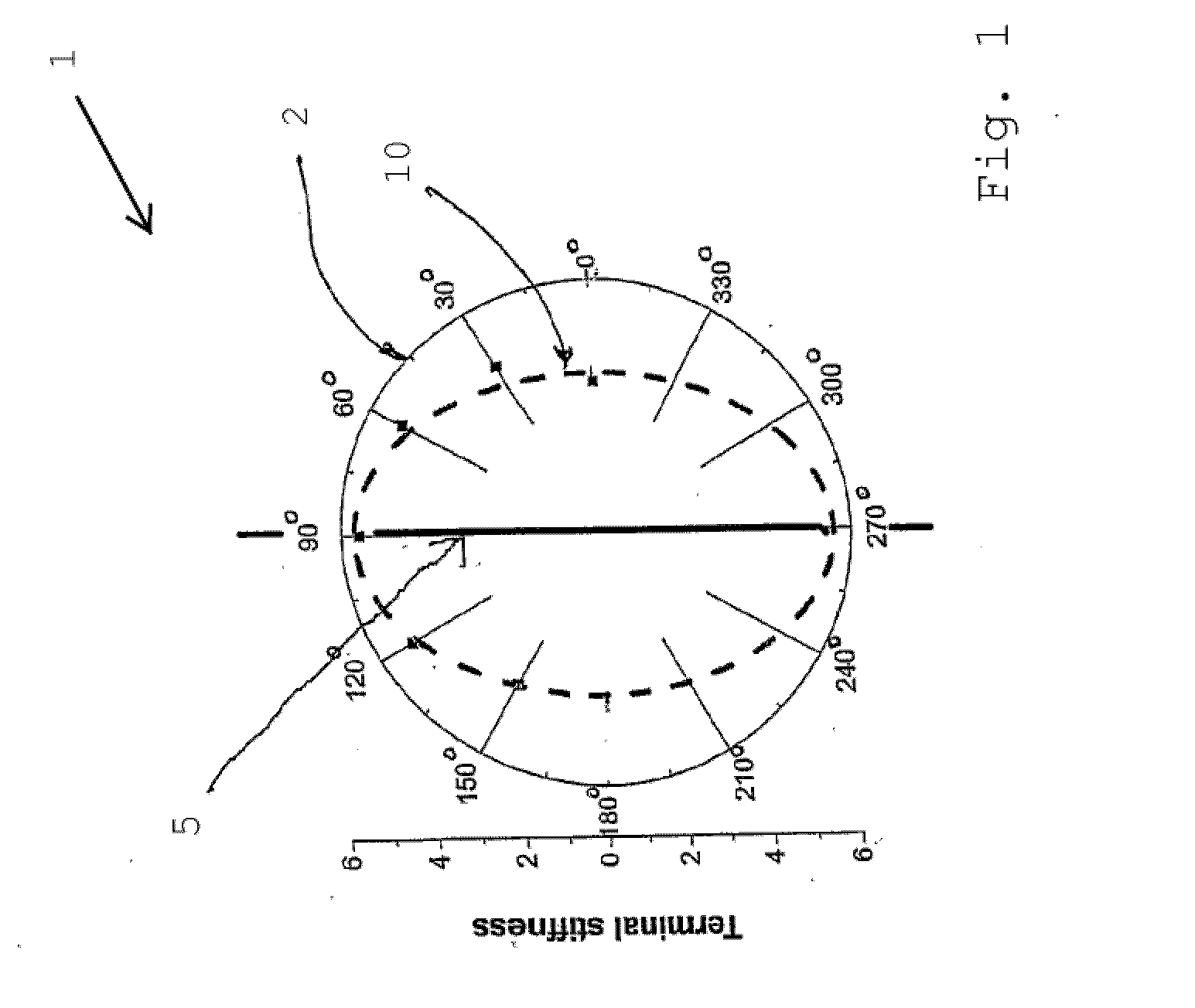
[0051]When the moduli of the high stiffness region of the stress-strain curves through a fixed point in various orientations are plotted in polar co-ordinates, the graph of mechanical properties with respect to testing direction is periodic. It is clear from FIG. 1 that these points join to form an ellipse shape 1.

[0052]These results substantiate the hypothesis that Langer's line 5 is the preferred orientation of the fibres within the reticular dermal tissue. The results as shown in FIG. 1 demonstrate that...


PUM


Abstract

An assembly for measuring in vivo biomechanical properties of skin, comprising a testing device, said testing device comprising; a first pad attachable to the skin a second pad attachable to the skin, at a known distance from the first pad; said attachability of the pads to the skin to prevent relative movement between the respective pad and the skin to which it is attached; a forcing means for applying a force to the first pad, whilst said pads are attached to the skin, along a first axis connecting the first and second pad, to induce a corresponding relative movement between the pads due to deformation of the skin between said pads; a force measurement device for measuring the applied force, and; a displacement measurement device for measuring the corresponding induced movement.

Description

CROSS REFERENCE TO RELATED APPLICATIONS[0001]This application is a divisional application of U.S. application Ser. No. 11 / 993,981, filed Dec. 27, 2007, which is itself a 35 U.S.C. 371 national phase application of International Application No. PCT / SG2006 / 000182, filed Jun. 29, 2006, which International Application was published by the International Bureau in English on Jan. 11, 2007, and claims priority to U.S. Application No. 60 / 695,747, filed Jun. 30, 2005, all of which are incorporated herein by reference in their entirety.FIELD OF INVENTION[0002]The invention relates to measurement of biomechanical properties of skin using a noninvasive approach.BACKGROUND[0003]Human skin provides the body with a flexible barrier to the exterior environment through a highly integrated layered structure consisting of epidermis, dermis and subcutaneous tissues. Each layer has its own specific structure and functions. Mechanical behaviour of the human skin is complex and well known to exhibit nonli...

Claims


Application Information

Patent Timeline
Patent Type & Authority Applications(United States)
IPC IPC(8): A61B5/11
CPCA61B5/0053A61B5/442G01N2203/0089G01N3/40G01N3/06
Inventor LIM, KENG HUIPOSTON, TIMOTHYHO, HOAN NGHIACHEW, CHEE MENGCHEN, CHAO YU PETERJEYAPALINA, SUJEEVINILIM, BENG HAI
Owner NAT UNIV OF SINGAPORE
Why Eureka
Try Eureka