Prosthetic foot with floating forefoot keel

a technology of prosthetic feet and keels, which is applied in the field of prosthetic feet, can solve the problems of limited material and imagination, and devices generally do not allow lateral rotation of the feet, and achieve the effect of soft feeling and more natural ankle rotation

Active Publication Date: 2011-12-29
FREEDOM INNOVATIONS INC
View PDF2 Cites 32 Cited by
  • Summary
  • Abstract
  • Description
  • Claims
  • Application Information

AI Technical Summary

Benefits of technology

[0008]It has been recognized that it would be advantageous to develop a prosthetic foot with a soft feel and more natural ankle rotation.

Problems solved by technology

With respect to prosthetic feet, the development of a functional and natural artificial foot has been limited by material and imagination.
Few designs consider the lateral, or side to side rotation of the foot when the foot is used on varied or uneven terrain.
Unfortunately, these devices generally do not allow for lateral rotation of the foot relative to the ankle.
Of devices that do allow lateral rotation, many unnaturally constrain the rotation, allow rotation only in discrete increments, or allow rotation in an unnatural manner.

Method used


Image

  • Prosthetic foot with floating forefoot keel
  • Prosthetic foot with floating forefoot keel
  • Prosthetic foot with floating forefoot keel

Examples


Embodiment Construction

)

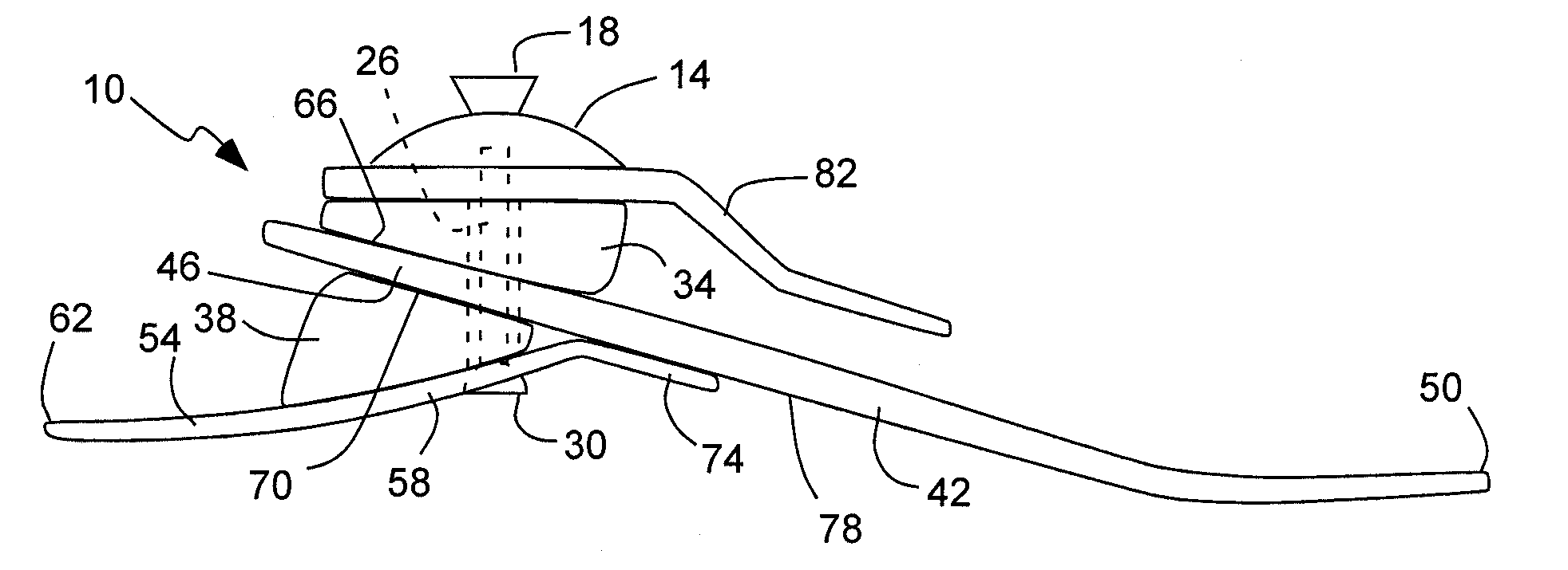
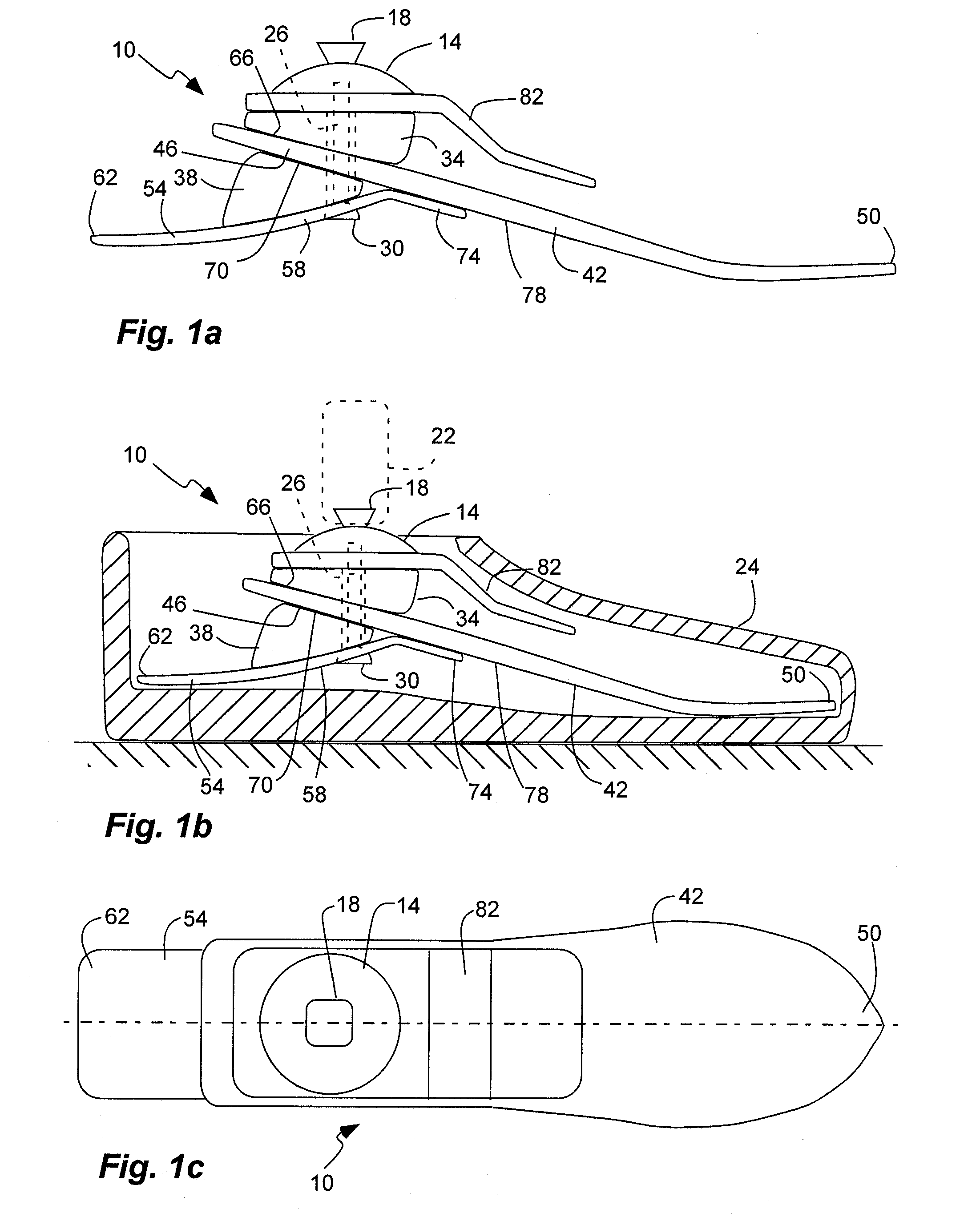
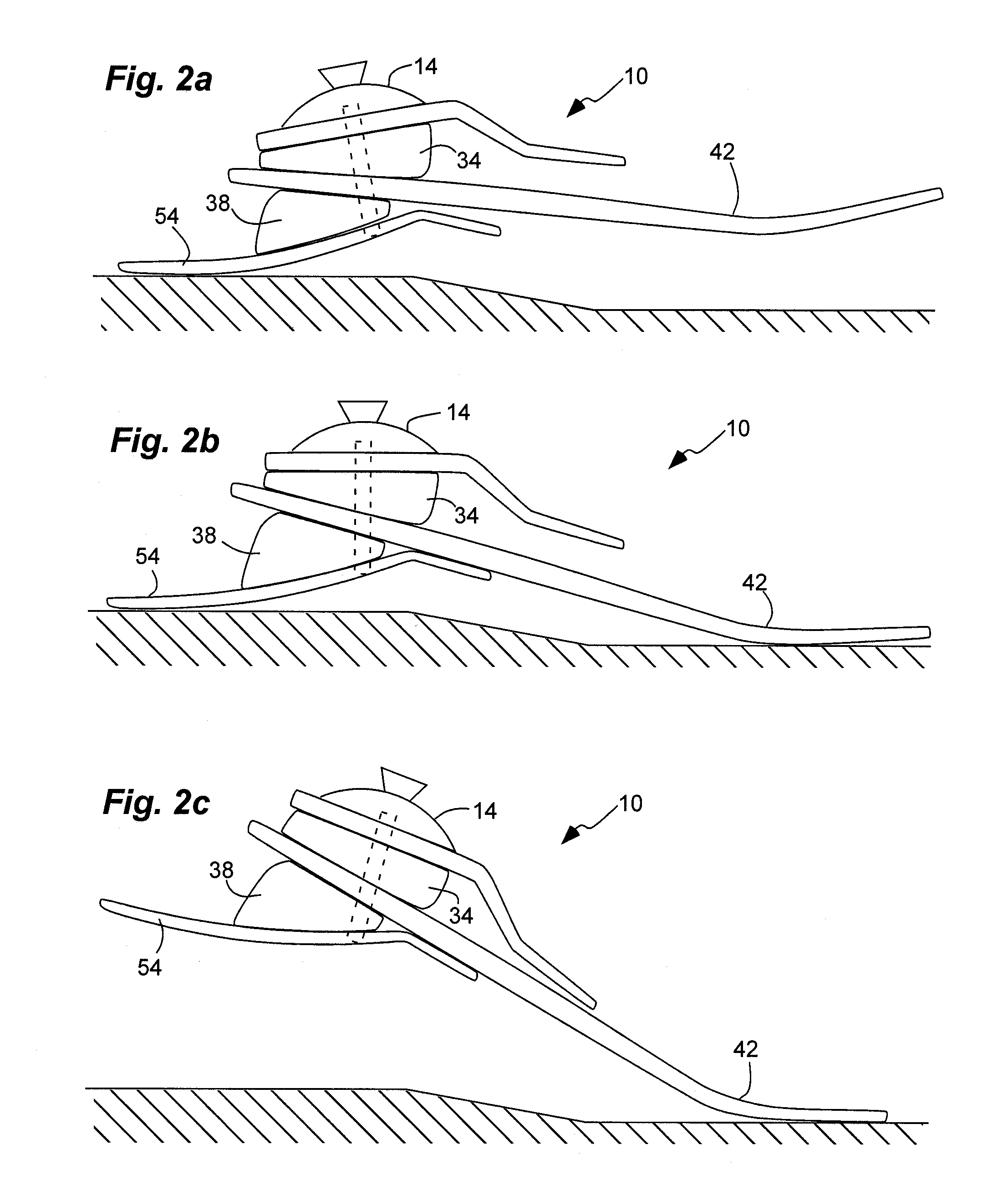
[0023]As illustrated in FIGS. 1a-2d, a prosthetic foot, indicated generally at 10, in an example implementation in accordance with the invention is shown. Such a foot can provide inversion / eversion rotation (side-to-side, inward and outward) of the foot and heel / toe rotation (longitudinal, front and back) of the foot. In addition, such a foot can provide various degrees of stiffness response.

[0024]The prosthetic foot 10 can have an attachment member 14 with an inverted pyramidal connector 18 (as is known in the art) coupled to a stump of an amputee, such as to a socket or pylon 22 (FIG. 2a). The foot can include a shell or can be disposed in a shoe, represented by 24, and which can provide an uneven surface, such as a higher heel with respect to the toe. An elongated vertical fastener 26 can be coupled to the attachment member 14. The fastener can extend to a head 30 spaced apart from and below the attachment member. The head can be semi-spherical or can have a semi-spherical or cu...


PUM


Abstract

A prosthetic foot device has an elongate forefoot spring carried by a fastener and suspended between upper and lower bumpers. A heel spring is suspended between an end of the fastener and the lower bumper.

Description

BACKGROUND[0001]1. Field of the Invention[0002]The present invention relates generally to prosthetic feet.[0003]2. Related Art[0004]Many individuals have lost a limb for various reasons including war, accident, or disease. In most instances these individuals are not only able to live relatively normal lives, but physically active lives as well. Oftentimes, these individuals are aided in their everyday lives by a prosthetic limb. The objective of prosthesis is to provide an artificial limb that simulates the function and natural feel of the replaced limb.[0005]With respect to prosthetic feet, the development of a functional and natural artificial foot has been limited by material and imagination. Many designs have attempted to copy the anatomy of the foot or simulate its actions by replacing the bones and muscle with various mechanical simulation by replacing the entire foot with an energy storage element such as a spring. As the user steps onto the foot, the user's weight compresses...

Claims


Application Information

Patent Timeline
Patent Type & Authority Applications(United States)
IPC IPC(8): A61F2/66
CPCA61F2/66A61F2002/665A61F2/6607
Inventor CHRISTENSEN, ROLAND J.GUERINOT, ALEXANDRE E.
Owner FREEDOM INNOVATIONS INC
Why Eureka
Try Eureka