Check patentability & draft patents in minutes with Patsnap Eureka AI!

Visualization of runtime analysis across dynamic boundaries

a dynamic boundary and runtime analysis technology, applied in software maintainance/management, instruments, program control, etc., can solve problems such as the inability to readily understand dynamic behavior from the static model

Active Publication Date: 2011-12-29
MICROSOFT TECH LICENSING LLC
View PDF2 Cites 9 Cited by
  • Summary
  • Abstract
  • Description
  • Claims
  • Application Information

AI Technical Summary

Benefits of technology

[0004]This Summary is not intended to identify key features or essential features of the claimed subject matter, nor is it intended to be used as an aid in determining the scope of the claimed subject matter.

Problems solved by technology

These dynamic behaviors may perhaps not be readily understood from the static model.

Method used


Image

  • Visualization of runtime analysis across dynamic boundaries
  • Visualization of runtime analysis across dynamic boundaries
  • Visualization of runtime analysis across dynamic boundaries

Examples


Embodiment Construction

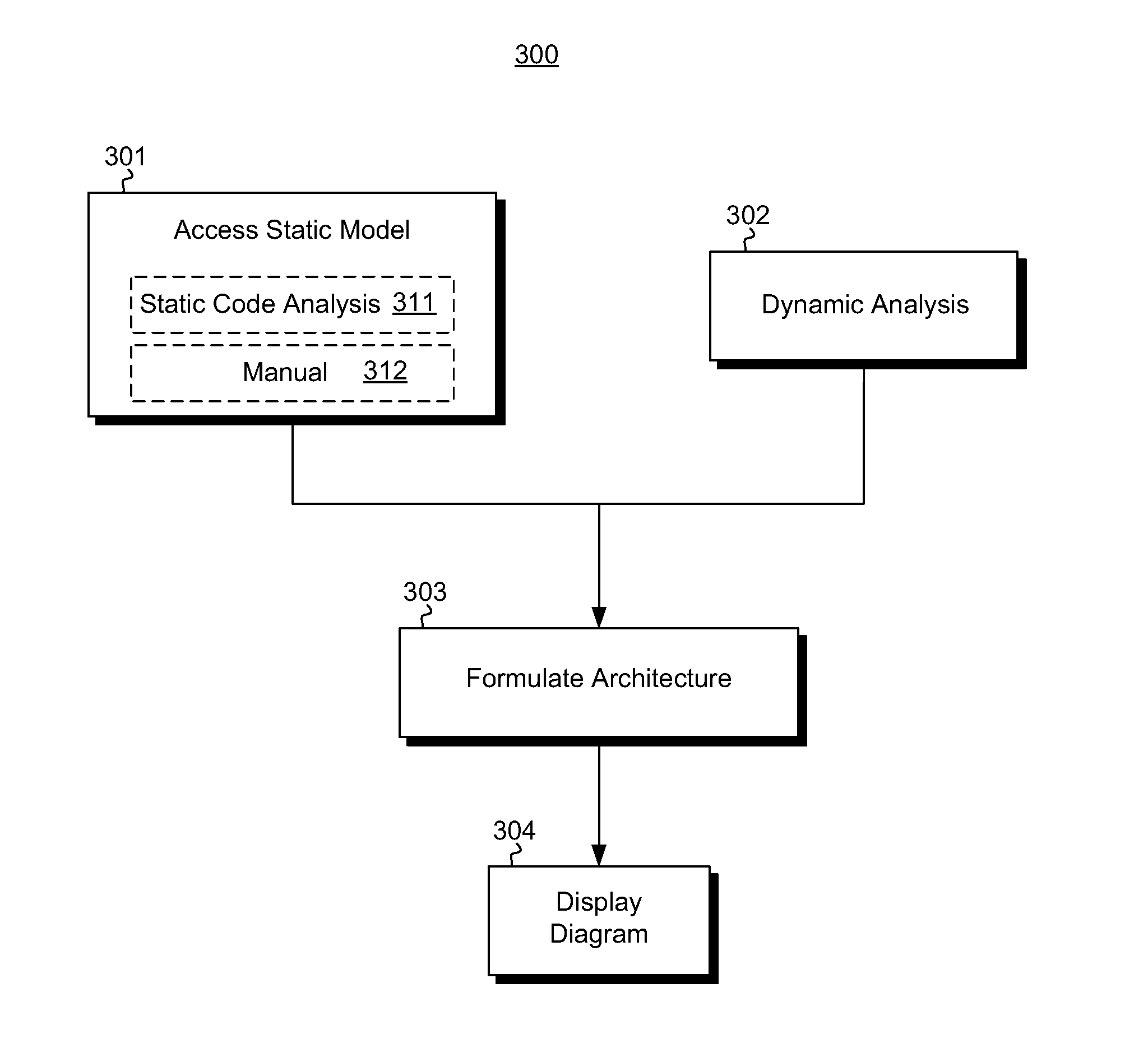
[0015]In accordance with embodiments described herein, the formulation of an architectural diagram of a software program having multiple components is described. A static model identifying at least some of the components and a relationship between the components is accessed by perhaps performing a static code analysis of the code of the software program. A dynamic analysis is also performed by executing the software program, and observing the execution to derive additional dynamic behaviors of the software program. These dynamic behaviors may perhaps not be readily understood from the static model alone, such as parameter values exchanged, paths of execution, and additional components invoked. The architectural diagram is then formulated using the static model and the dynamic behaviors to generate a more complete representation of the computer program.

[0016]First, some introductory discussion regarding computing systems will be described with respect to FIG. 1. Then, the embodiments...


PUM


Abstract

The formulation of an architectural diagram of a software program having multiple components. A static model identifying at least some of the components and a relationship between the components is accessed by perhaps performing a static code analysis of the code of the software program. A dynamic analysis is also performed by executing the software program, and observing the execution to derive dynamic behaviors of the software program. These dynamic behaviors may perhaps be information that is not readily available based on a static code analysis of the computer program alone, such as parameter values exchanged, paths of execution, and additional components invoked. The architectural diagram is then formulated using the static model and the dynamic behaviors to generate a more complete representation of the computer program.

Description

BACKGROUND[0001]The functionality offered by software is becoming ever more complex. Architectural diagrams are used to provide an overview of the functionality and / or structure of software. There are a variety of types of architectural diagrams used for software. Common amongst all these architectural diagrams is some visual representation of multiple components of the software, along with some visualization of relationships between the components. The Unified Modeling Language (UML) is a standardized modeling language and includes a set of graphical notation techniques to create visualizations of software-intensive systems. The UML defines a number of different types of architectural diagrams.[0002]Architectural diagrams have historically first been constructed manually, in which an author draws the diagram to highlight a design or requirement of the software. More recently, automated generation of architectural diagrams is employed. Such automated systems perform a static code an...

Claims


Application Information

Patent Timeline
Patent Type & Authority Applications(United States)
IPC IPC(8): G06F9/44
CPCG06F8/75G06F11/3604G06F11/323
Inventor DUTTA, SUHAILCRAWFORD, BRIAN ROBERTCONANT, ELLIOTT ROSS
Owner MICROSOFT TECH LICENSING LLC
Features
  • R&D
  • Intellectual Property
  • Life Sciences
  • Materials
  • Tech Scout
  • Unparalleled Data Quality
  • Higher Quality Content
  • 60% Fewer Hallucinations
Learn More