Recognizing gestures and using gestures for interacting with software applications

a software application and gesture recognition technology, applied in the field of recognition gestures and using gestures for interacting with software applications, can solve the problems of not being able to detect the location of more than one finger or object at the same time, prior art systems of these types cannot detect patterns on objects or detailed shapes

Inactive Publication Date: 2006-01-12
MICROSOFT TECH LICENSING LLC
View PDF26 Cites 849 Cited by
  • Summary
  • Abstract
  • Description
  • Claims
  • Application Information

AI Technical Summary

Problems solved by technology

Capacitive, electromagnetic, optical, or other types of sensors used in conventional touch-sensitive displays typically cannot simultaneously detect the location of more than one finger or object touching the display screen at a time.
Capacitive or resistive, or acoustic surface wave sensing display surfaces that can detect multiple points of contact are unable to image objects on a display surface to with any degree of resolution.
Prior art systems of these types cannot detect patterns on an object or detailed shapes that might be used to identify each object among a plurality of different objects that are placed on a display surface.
This multiple camera mounting configuration is clearly not a compact system that most people would want to use in a residential setting.
Furthermore, the view of one object by one of the cameras may be blocked by an intervening object.
However, these two prior art systems suffer with the same limitations as other touch sensitive, capacitive, or electromagnetic sensitive display surfaces—i.e., the lack of good imaging resolution, the inability to properly distinguish shape and orientation of objects, and the difficulty in sensing multiple object in contact with the display surface at one time.
Also, a pressure sensitive display surface requires actual contact with the display surface and cannot respond to objects that are in proximity with the display surface.

Method used


Image

  • Recognizing gestures and using gestures for interacting with software applications
  • Recognizing gestures and using gestures for interacting with software applications
  • Recognizing gestures and using gestures for interacting with software applications

Examples


Embodiment Construction

Exemplary Computing System for Implementing Present Invention

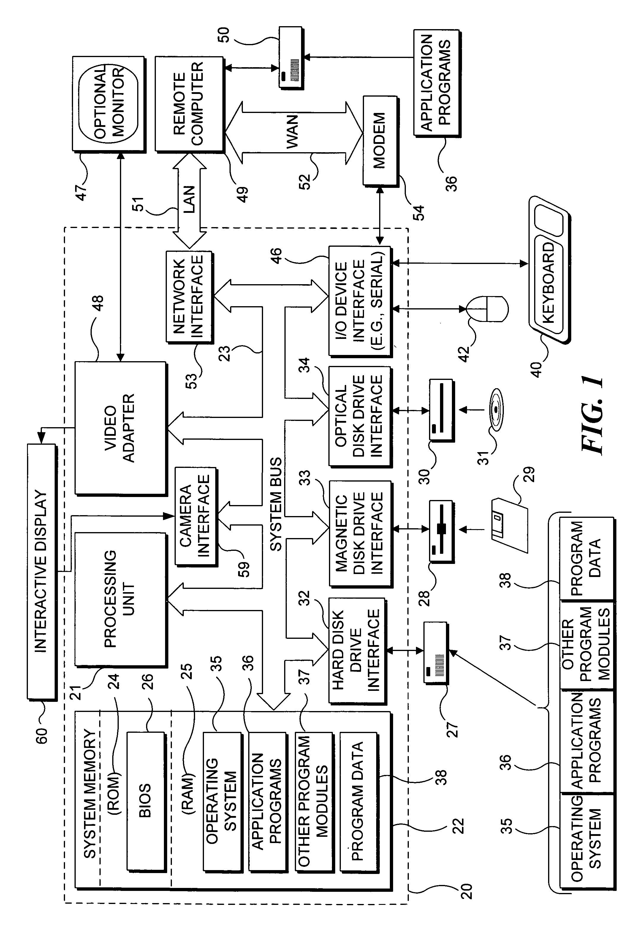
[0040] With reference to FIG. 1, an exemplary system suitable for implementing various portions of the present invention is shown. The system includes a general purpose computing device in the form of a conventional PC 20, provided with a processing unit 21, a system memory 22, and a system bus 23. The system bus couples various system components including the system memory to processing unit 21 and may be any of several types of bus structures, including a memory bus or memory controller, a peripheral bus, and a local bus using any of a variety of bus architectures. The system memory includes read only memory (ROM) 24 and random access memory (RAM) 25. A basic input / output system 26 (BIOS), containing the basic routines that help to transfer information between elements within the PC 20, such as during start up, is stored in ROM 24. PC 20 further includes a hard disk drive 27 for reading from and writing to a hard disk ...


PUM


Abstract

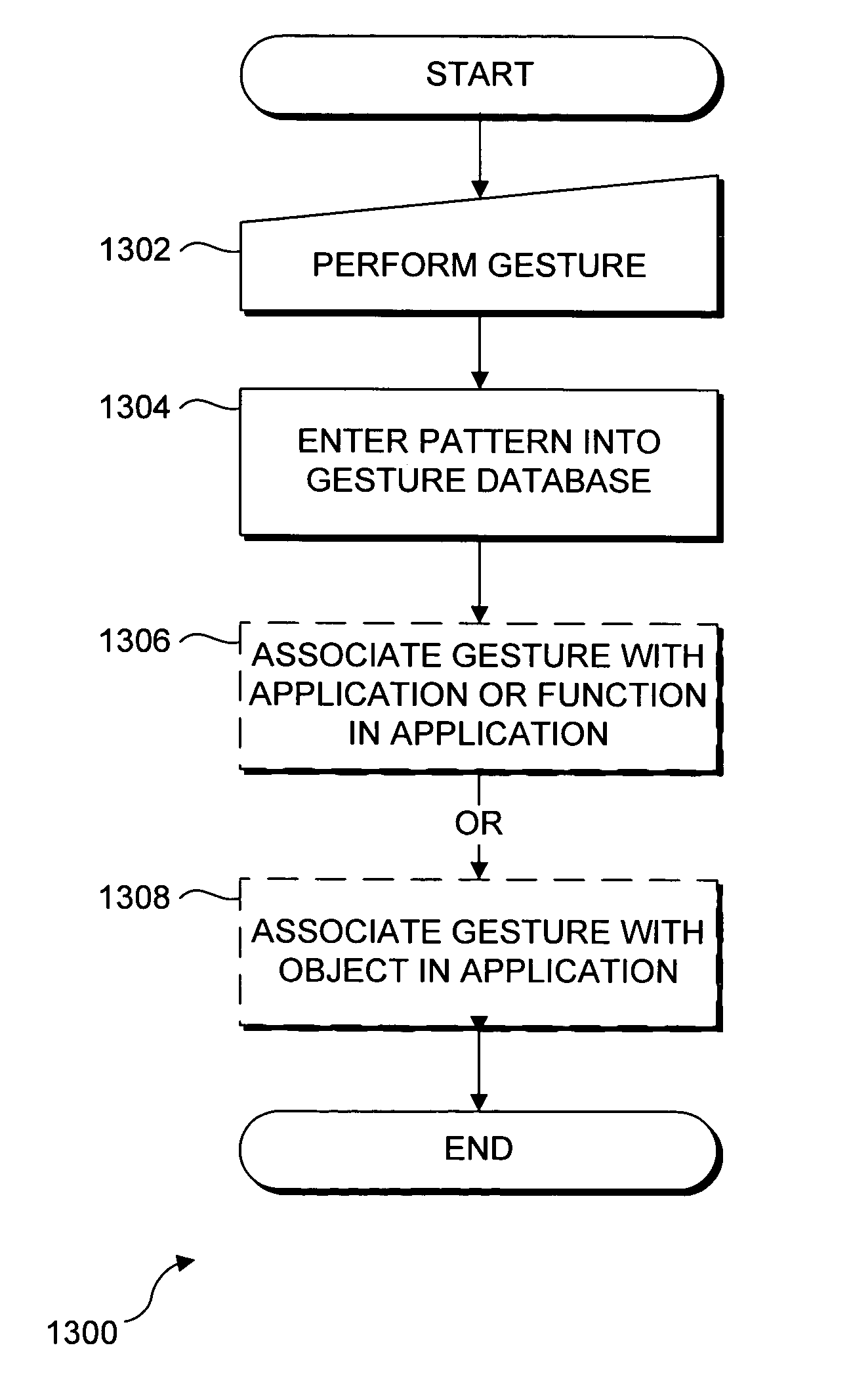
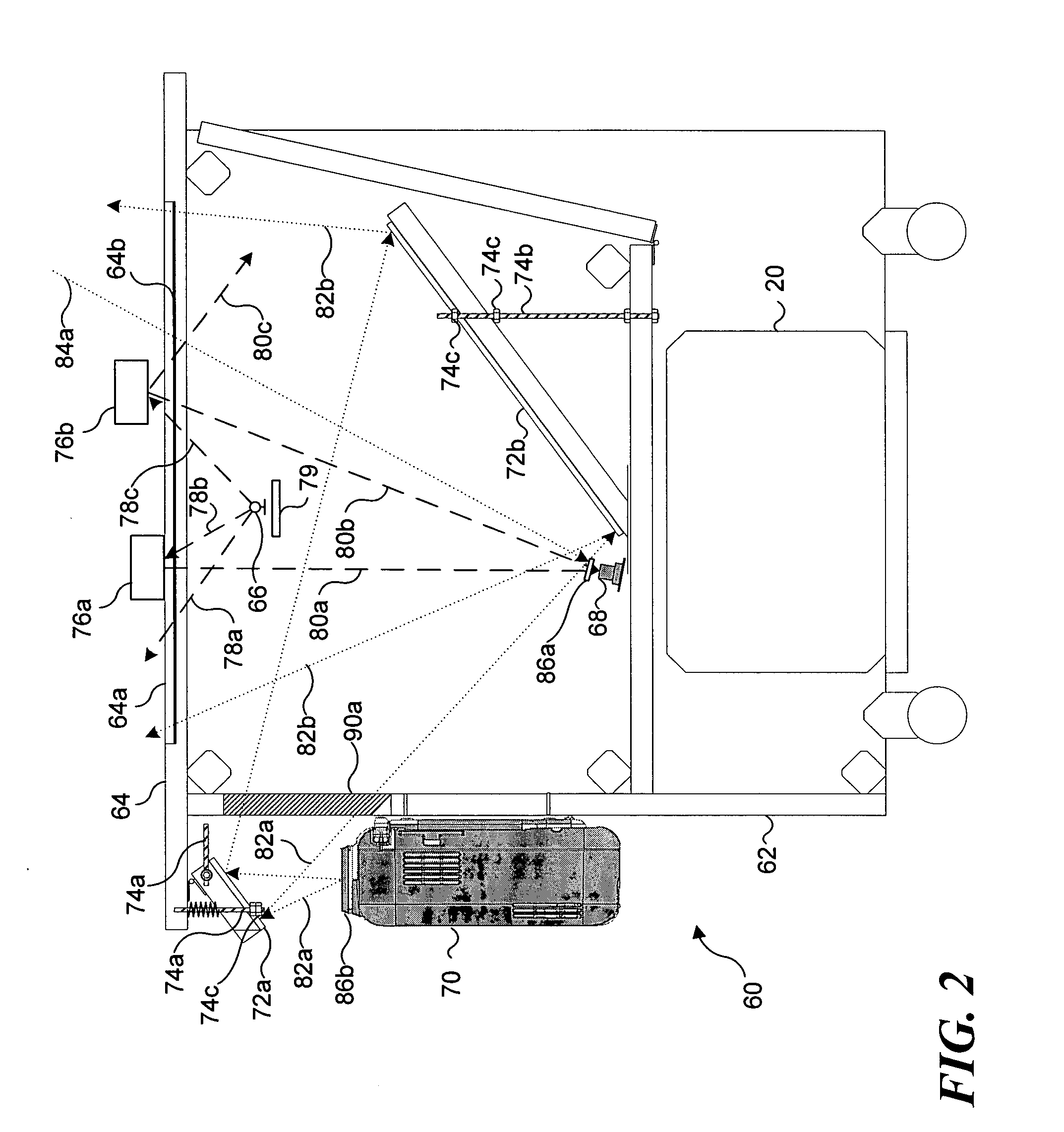
An interactive display table has a display surface for displaying images and upon or adjacent to which various objects, including a user's hand(s) and finger(s) can be detected. A video camera within the interactive display table responds to infrared (IR) light reflected from the objects to detect any connected components. Connected component correspond to portions of the object(s) that are either in contact, or proximate the display surface. Using these connected components, the interactive display table senses and infers natural hand or finger positions, or movement of an object, to detect gestures. Specific gestures are used to execute applications, carryout functions in an application, create a virtual object, or do other interactions, each of which is associated with a different gesture. A gesture can be a static pose, or a more complex configuration, and / or movement made with one or both hands or other objects.

Description

FIELD OF THE INVENTION [0001] This invention generally pertains to a method and apparatus for detecting gestures made with a user's hands and fingers to interact with a virtual environment displayed on an interactive display surface, and more specifically, pertains to controlling software applications or the display of images on the display surface using natural hand or finger motions proximate to the display surface. BACKGROUND OF THE INVENTION [0002] The interaction between computing devices and users continues to improve as computing platforms become more powerful and able to respond to a user in many new and different ways, so that a user is not required to type on a keyboard in order to control applications and input data. The development of a graphic user interface system, like that provided by Microsoft Corporation's WINDOWS™ operating system, has greatly improved the ease with which a user can interact with a computing device, by enabling a user to input control actions and ...

Claims


Application Information

Patent Timeline
Patent Type & Authority Applications(United States)
IPC IPC(8): G06F13/00
CPCG06F3/0354G06F3/0421G06K9/00355G06F2203/0382G06F2203/04808G06F3/04883G06V40/28
Inventor DEHLIN, JOEL P.CHEN, CHRISTINA SUMMERWILSON, ANDREW D.ROBBINS, DANIEL C.HORVITZ, ERIC J.HINCKLEY, KENNETH P.WOBBROCK, JACOB O.
Owner MICROSOFT TECH LICENSING LLC
Why Eureka
Try Eureka