Robot system

a robot and system technology, applied in the field of robot systems, can solve the problems of troublesome work, difficulty in checking welding points, troublesome work, etc., and achieve the effect of bending the amount of workpieces, easy correction of teaching points, and easy adjustment of welding points

Inactive Publication Date: 2012-01-05
YASKAWA DENKI KK
View PDF25 Cites 38 Cited by
  • Summary
  • Abstract
  • Description
  • Claims
  • Application Information

AI Technical Summary

Benefits of technology

[0019]With the aspect of the present invention, since the movable electrode of the spot welding gun and the respective axes of the robot are automatically operated, and the positions of the movable electrode and respective axes when the movable electrode and the fixed electrode actually apply the pressure to the workpiece are stored, the teaching can be made without previously setting the plate thickness of the workpiece. Even if the plate thickness is changed because, for example, a production line is changed, the teach point can be easily corrected.
[0020]Also, as compared with the related art, the teaching in the state, in which the bending amount of the workpiece due to the contact with respect to the movable electrode and the fixed electrode is reduced, can be made, and the spot welding can be properly performed. This makes a contribution to improvement for the welding quality.
[0021]Further, since the extension amount of the movable electrode is checked when the teaching is made; the error of the workpiece can be reliably detected.

Problems solved by technology

However, if a workpiece has a complex shape; a setup person has difficulty in checking the welding points during the teaching work.
The teaching work for the robot may need a time and may be troublesome work.
Also, if the robot is incorrectly operated, there may be a problem in which the electrodes collide with the workpiece, resulting in that the workpiece and the robot may be broken.

Method used


Image

  • Robot system
  • Robot system
  • Robot system

Examples


Embodiment Construction

[0038]Embodiments will now be described with reference to the accompanying drawings, wherein like reference numerals designate corresponding or identical elements throughout the various drawings.

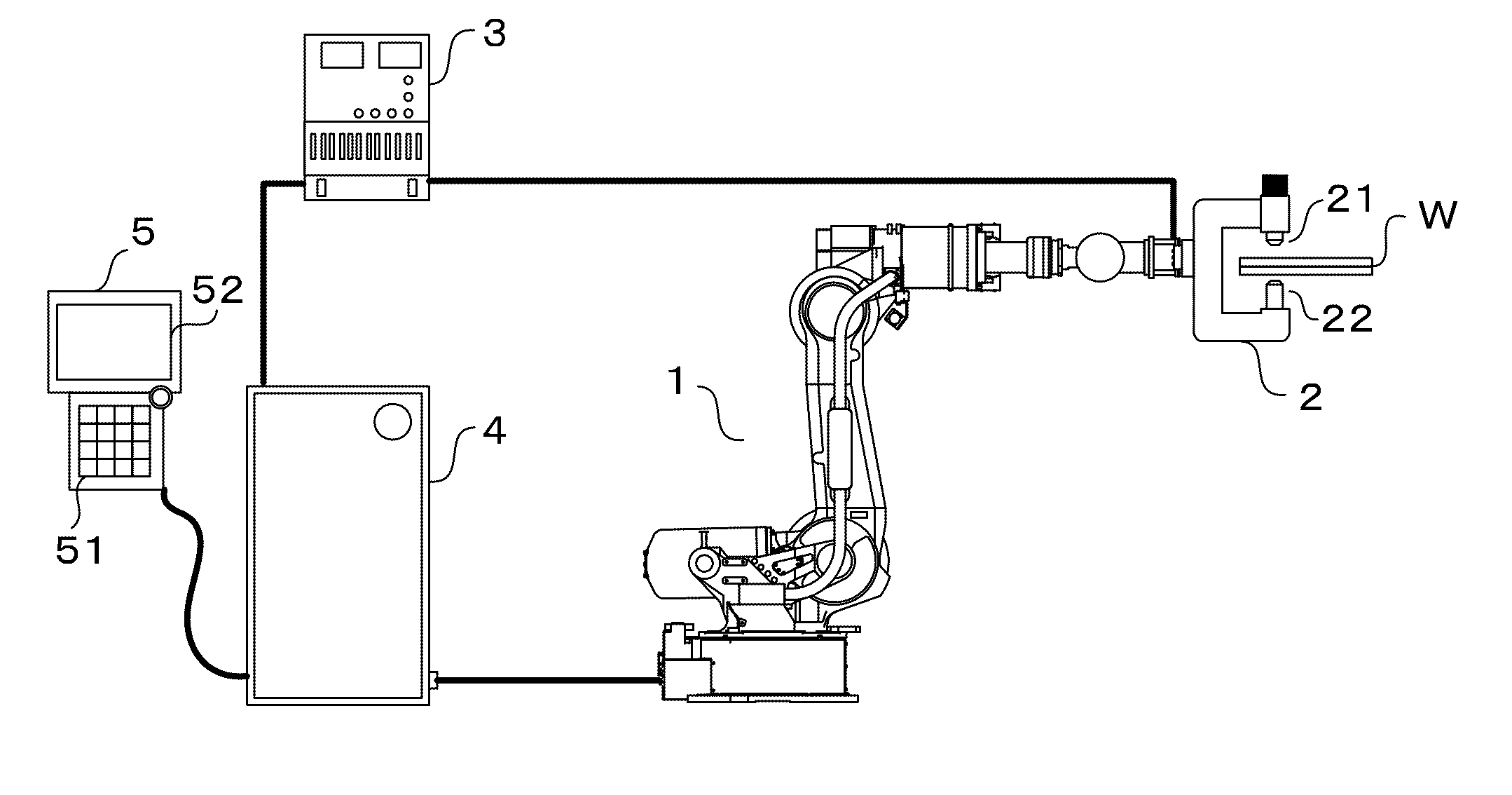
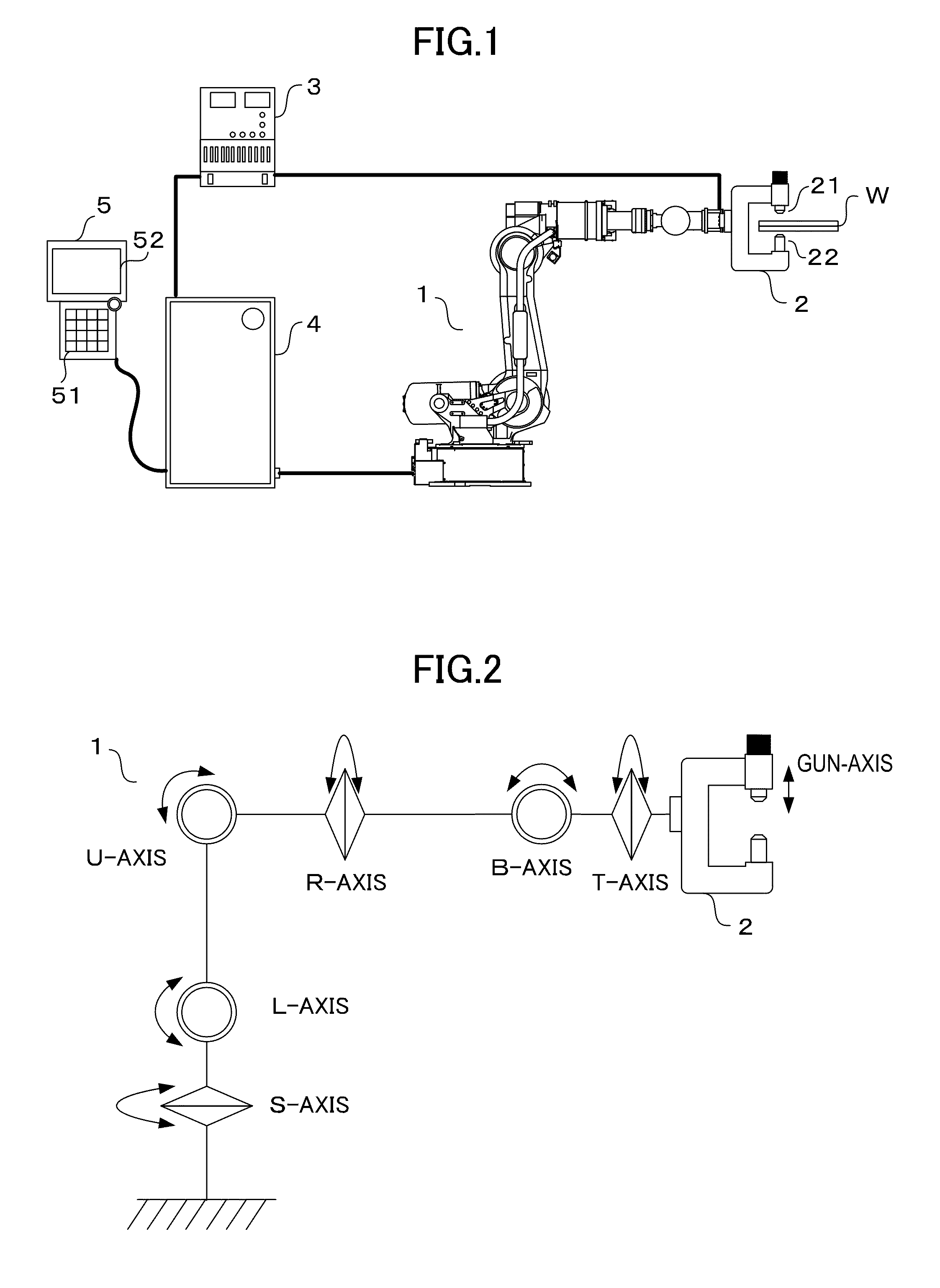
[0039]FIG. 1 schematically illustrates a configuration of a robot system according to this embodiment.

[0040]Referring to FIG. 1, a vertical articulated robot 1 has a plurality of joint-axes. A spot welding gun 2 is attached to a tip end of the robot 1.

[0041]The spot welding gun 2 includes a movable electrode 21 and a fixed electrode 22 that are arranged opposite to each other. In the illustrated example, two electrodes are vertically arranged, and the upper electrode is the movable electrode 21, and the lower electrode is the fixed electrode 22. When spot welding is performed, the movable electrode 21 is extended toward the fixed electrode 22 while a member to be welded (workpiece) W is arranged between the movable electrode 21 and the fixed electrode 22, the movable electrode 21 and the fix...


PUM

PropertyMeasurementUnit
degree of freedomaaaaaaaaaa
ripple frequencyaaaaaaaaaa

Abstract

For teaching a welding-point position for a robot, processing of a robot system includes first processing for moving a spot welding gun to a position at which movable and fixed electrodes pinch the welding point; second processing for extending the movable electrode toward a member to be welded by driving of a motor, detecting contact between the movable electrode and the member based on a torque command to the motor, and stopping the movable electrode after the contact is detected; and third processing for operating the robot toward the movable electrode to move the fixed electrode toward the member while maintaining the contact between the movable electrode and the member by the driving of the motor, detecting contact between the fixed electrode and the member based on a disturbance torque acting on a joint of the robot, and stopping the operation of the robot after the contact is detected.

Description

CROSS-REFERENCE TO RELATED APPLICATIONS[0001]The present application claims priority under 35 U.S.C. §119 to Japanese Patent Application No. 2010-148575 filed Jun. 30, 2010. The contents of the application are incorporated herein by reference in their entirety.BACKGROUND OF THE INVENTION[0002]1. Field of the Invention[0003]The present invention relates to a robot system that performs predetermined work by using a robot, and more particularly relates to a robot system that performs spot welding.[0004]2. Description of the Related Art[0005]For spot welding in which a pair of electrodes pinch a plurality of stacked workpieces from both sides in a stacking direction and current is applied between the electrodes while a pressure is applied, a spot welding robot having a spot welding gun attached to a tip end of the robot has been known as related art. Spot welding work can be performed while the spot welding gun is moved successively to a plurality of welding points on the workpieces by ...

Claims


Application Information

Patent Timeline
Patent Type & Authority Applications(United States)
IPC IPC(8): B23K37/02
CPCB23K11/115
Inventor NAKANISHI, MITSUAKIWADA, MAKOTO
Owner YASKAWA DENKI KK
Why Eureka
Try Eureka