Light source apparatus for fluorescence photography

Active Publication Date: 2012-01-05
YAYATECH
View PDF3 Cites 3 Cited by
  • Summary
  • Abstract
  • Description
  • Claims
  • Application Information

AI Technical Summary

Benefits of technology

[0015]It is still another objective of the present invention to provide a light source apparatus for fluoresce

Problems solved by technology

It is difficult to detect or analyze the phosphorylated proteins before pre-concentration process.
However, due to structural limitation, one apparatus is suitable for exciting light

Method used


Image

  • Light source apparatus for fluorescence photography
  • Light source apparatus for fluorescence photography
  • Light source apparatus for fluorescence photography

Examples


Embodiment Construction

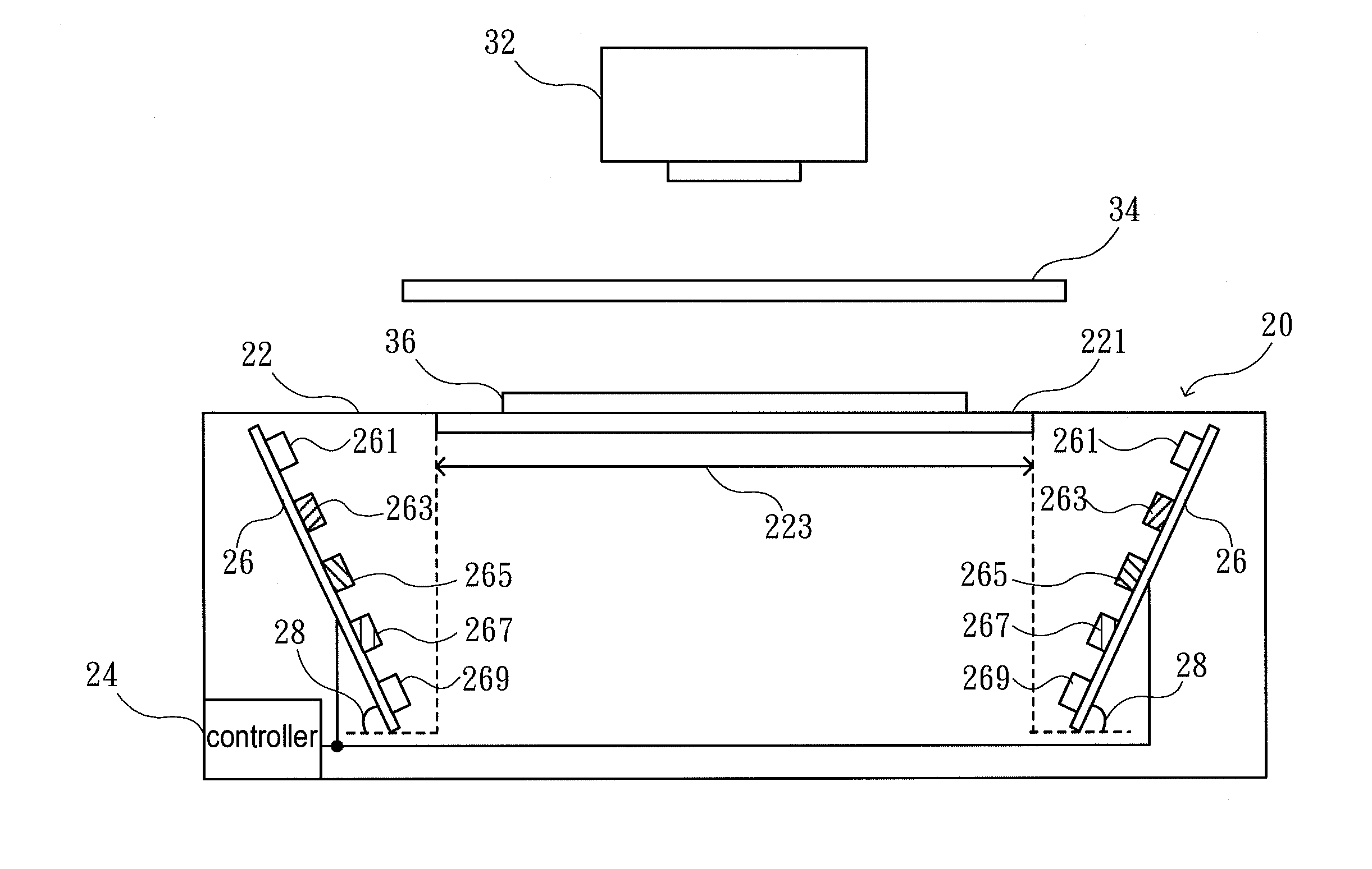
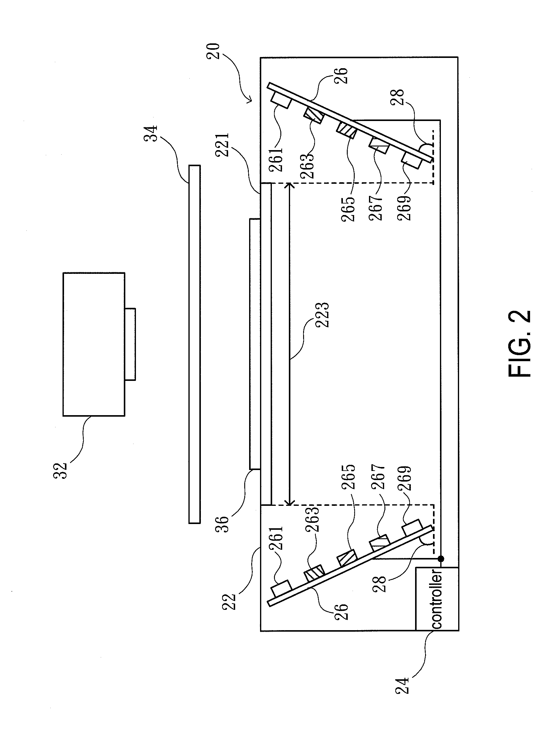
[0020]Referring to FIG. 2, there is shown a light source apparatus 20 for fluorescence photography in accordance with the present invention. The light source apparatus 20 comprises a housing 22, a transparent plate 221 and at least one LED array 26.

[0021]The housing 22 has a light transmission zone 223 located on the top thereof. The transparent plate 221 is disposed in the light transmission zone 223 of the housing 22 for supporting a biomolecule sample gel 36. The at least one LED array 26 is disposed inside the housing 22 out of the range of the light transmission zone 223. The exciting light is projected to the light transmission zone 223 and the transparent plate 221 obliquely for preventing the light spots of the LED from interfering in fluorescence photographing or observation.

[0022]The transparent plate 221 disposed in the light transmission zone 223 allows different colors of exciting light or ultraviolet light to pass through and irradiate the biomolecule sample gel 36 dir...


PUM


Abstract

A light source apparatus for fluorescence photography of biomolecule sample gels is disclosed. The light source apparatus comprises a housing, a transparent plate disposed in a light transmission zone at the top of the housing, and at least one LED array disposed in the housing out of the range of the light transmission zone. The LED array irradiates obliquely to the light transmission zone for preventing the light spots from interfering in the observation. Each of LED array may comprises different colors of LEDs for different biomolecule samples.

Description

BACKGROUND OF THE INVENTION[0001]The present invention relates to a light source apparatus for fluorescence photography, and more particularly to a light source apparatus for fluorescence photography of biomolecule sample gels.[0002]In biotechnology experiments, to all eukaryotes, protein phosphorylation can cause the organism to change the activation of the intracellular protein or enzyme, transmit signal, or regulate cell physiological processes such as cell metabolism, cell growth, cell proliferation or cell cancerization. However, the content of phosphorylated proteins in organism is extremely low and normally kept in a dynamic balance status. It is difficult to detect or analyze the phosphorylated proteins before pre-concentration process.[0003]Western blotting was introduced by Towbin et. al. in 1979 and is now a routine technique for protein analysis. The specificity of the antibody-antigen interaction enables a target protein to be identified in the midst of a complex protei...

Claims


Application Information

Patent Timeline
IPC IPC(8): G01N21/64G01J1/58
CPCG01J1/08G01J1/58G01N2201/0627G01N2021/6419G01N21/6456
Inventor YAN, SHUO-TINGHONG, WEI-LITSAI, YUAN YU
Owner YAYATECH
Why Eureka
Try Eureka