
Plasma display apparatus and driving method thereof

a technology of plasma display and display screen, which is applied in the direction of instruments, static indicating devices, etc., can solve problems such as wrong discharge generation, and achieve the effects of preventing screen distortion, preventing spots from appearing, and suppressing the occurrence of afterimage-generating wrong discharg

Inactive Publication Date: 2007-01-18
LG ELECTRONICS INC
View PDF14 Cites 4 Cited by
  • Summary
  • Abstract
  • Description
  • Claims
  • Application Information

AI Technical Summary

Benefits of technology

[0033] The present invention provides a plasma display apparatus which is capable of preventing an afterimage-generating wrong discharge.
[0044] Furthermore, according to the present invention, it is possible to prevent a complementary color afterimage from appearing on a displayed image.

Problems solved by technology

However, during the address period, a wrong discharge is generated between the scan electrode Y and the sustain electrode Z by the wall charges fixed during the set-down period and the charged particles diffused from the neighboring cells.

Method used


Image

  • Plasma display apparatus and driving method thereof
  • Plasma display apparatus and driving method thereof
  • Plasma display apparatus and driving method thereof

Examples


first embodiment

[0084]FIG. 4 is a view for explaining the structure of a plasma display apparatus according to a first embodiment of the present invention.

[0085] Referring to FIG. 4, the plasma display apparatus according to the first embodiment of the present invention includes a plasma display panel 400, a data driver 410, a scan driver 420, a sustain driver 430, a driving pulse controller 440, and a driving voltage generator 450.

[0086] A plurality of scan electrodes Y1 through Yn, a plurality of sustain electrodes Z, and a plurality of address electrodes X1 through Xm which intersect the scan electrodes Y1 through Yn and the sustain electrodes Z, are formed on the plasma display panel 400.

[0087] The data driver 410 applies data to the address electrodes X1 through Xm formed on the plasma display panel 400, wherein the data is image signal data obtained by processing an image signal received from the outside in an image signal processor (not shown). The data driver 410 samples and latches data...

second embodiment

[0137]FIG. 9 is a view for explaining the structure of a plasma display apparatus according to a second embodiment of the present invention.

[0138] As shown in FIG. 9, the plasma display apparatus according to the second embodiment of the present invention includes a plasma display panel 900, a data driver 910, a scan driver 920, a sustain driver 930, a driving pulse controller 940, and a driving voltage generator 950.

[0139] A plurality of scan electrodes Y1 through Yn, a plurality of sustain electrodes Z, and a plurality of address electrodes X1 through Xm which intersect the scan electrodes Y1 through Y1 and the sustain electrodes Z, are formed on the plasma display panel 900.

[0140] The data driver 910 applies data to the address electrodes X1 through Xm formed on the plasma display panel 900, wherein the data is image signal data obtained by processing an image signal received from the outside in an image signal processor (not shown). The data driver 910 samples and latches dat...


PUM


Abstract

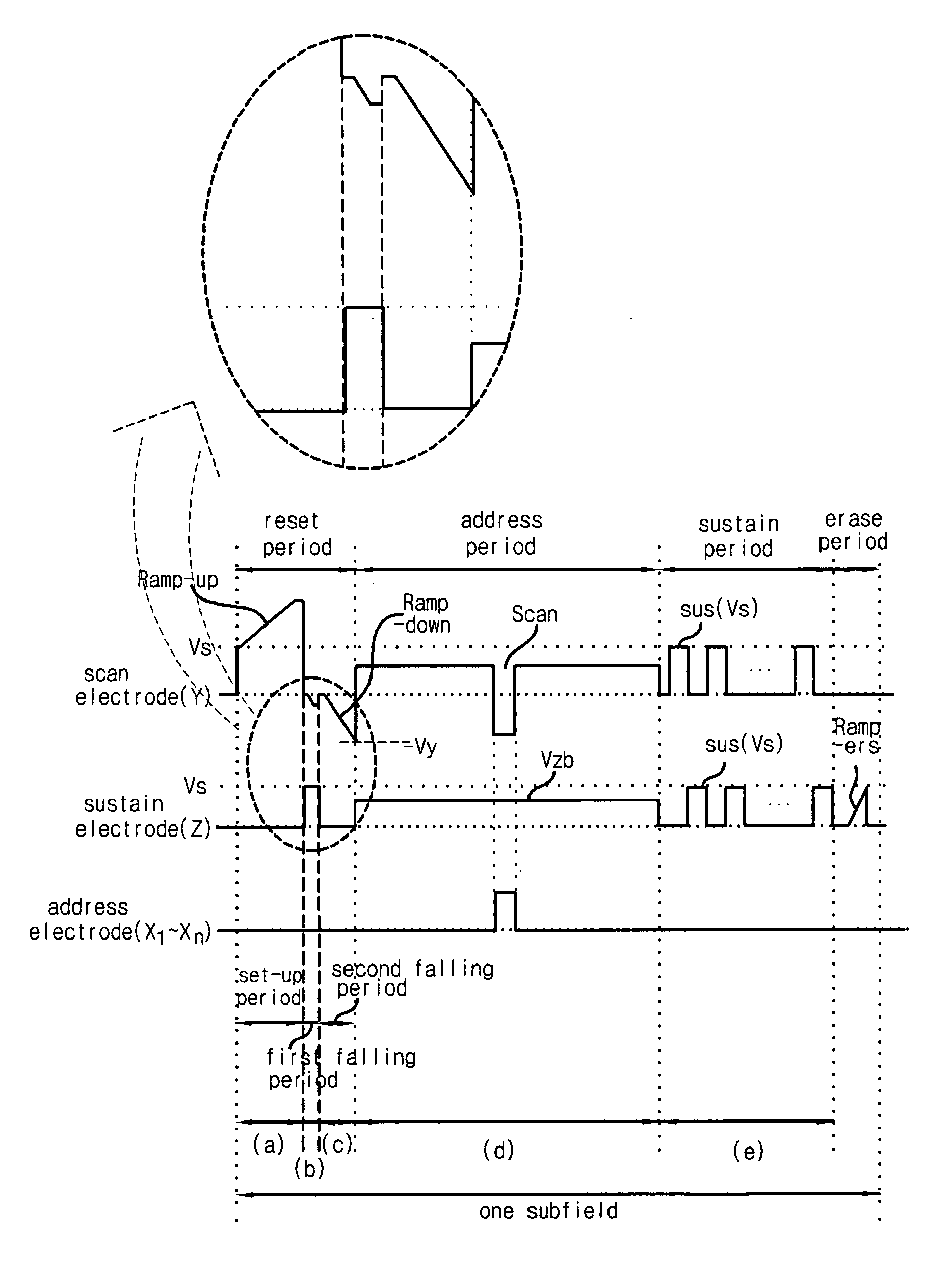
The present invention relates to a plasma display apparatus, and more particularly to a plasma display apparatus and a driving method thereof, which are capable of preventing an afterimage-generating wrong discharge when a plasma display panel is driven. Provided is a plasma display apparatus, including: a plasma display panel on which a plurality of sustain electrode pairs, each including a scan electrode and a sustain electrode, are formed; a driver driving each sustain electrode pair; and a driving pulse controller which controls the driver to sequentially apply a first falling waveform and a second falling waveform to the scan electrode and to apply a positive waveform to the sustain electrode while applying the first falling waveform, in a reset period. In accordance with the present invention, it is possible to prevent afterimage-generating woring discharge by improving the structure of a plasma display apparatus and a driving method thereof. In accordance with the present invention, it is possbiel to prevent spots from being created on a displayed single color pattern by improving the structure of a plasma display apparatus and a driving method thereof.

Description

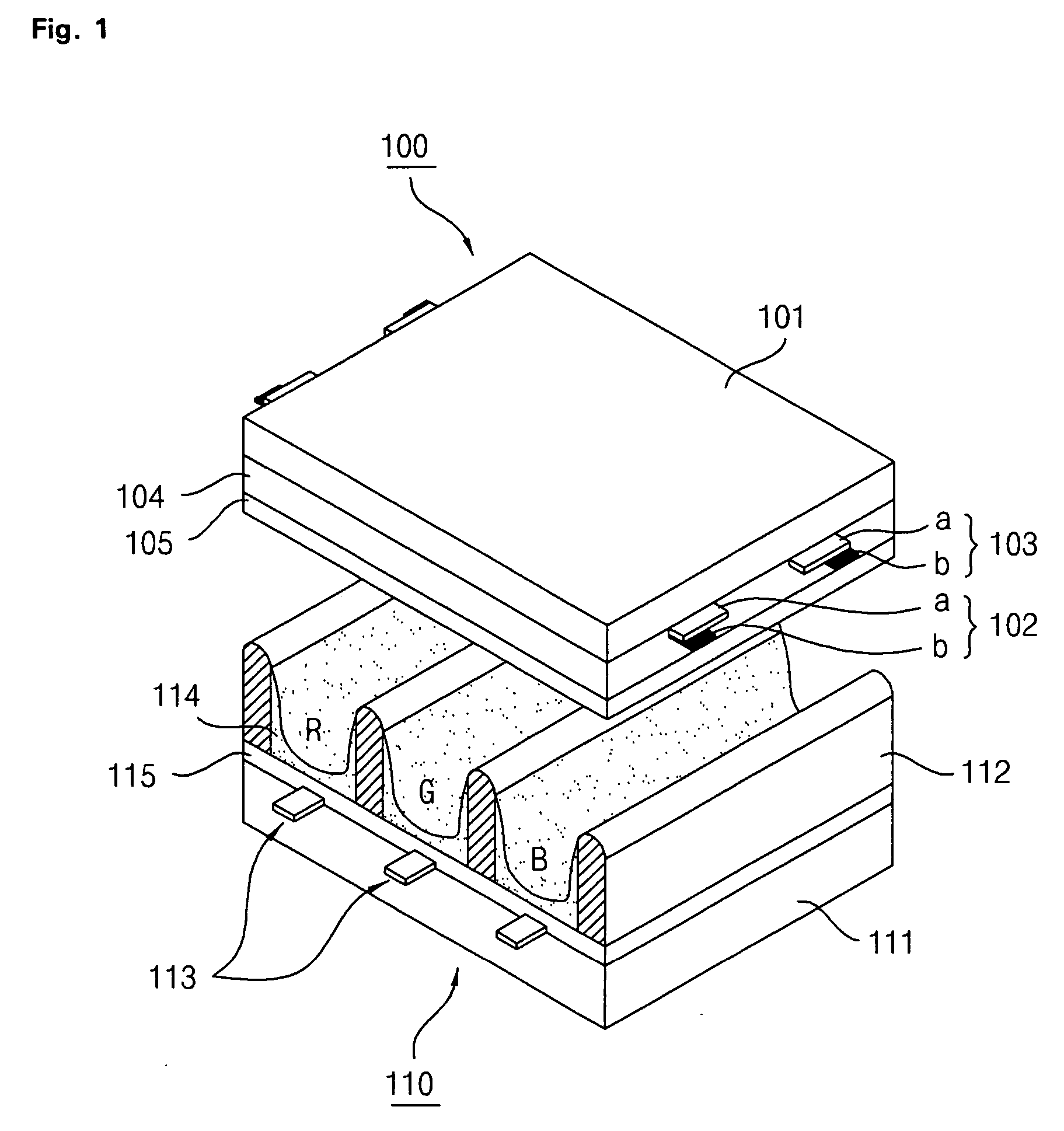
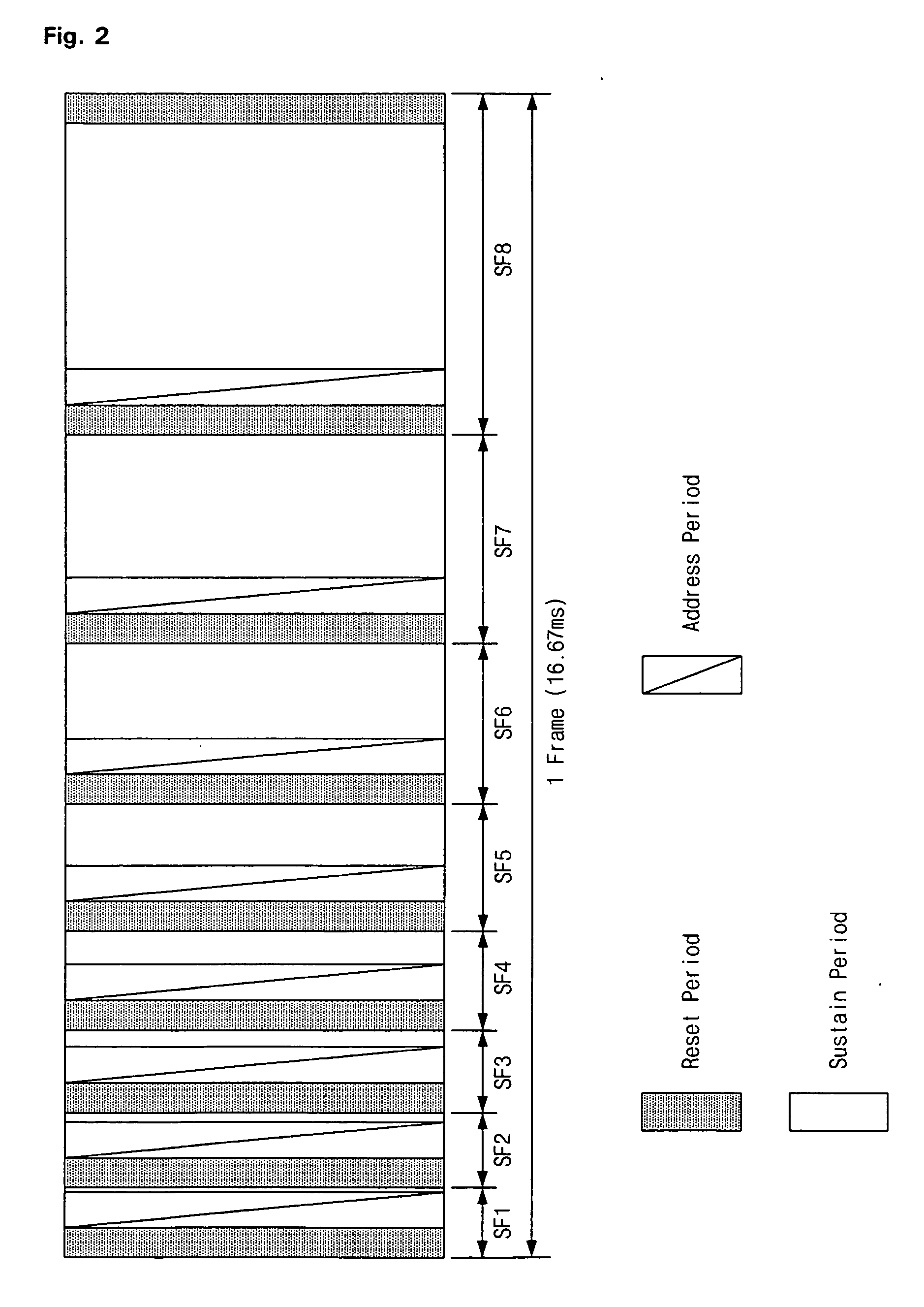
[0001] This Nonprovisional application claims priority under 35 U.S.C. § 119(a) on Patent Application No. 10-2005-0064045 filed in Korea on Jul. 15, 2005, the entire contents of which are hereby incorporated by reference. BACKGROUND OF THE INVENTION [0002] 1. Field of the Invention [0003] The present invention relates to a plasma display apparatus, and more particularly, to a plasma display apparatus which is capable of preventing an afterimage-generating wrong discharge from occurring when a plasma display panel is driven. [0004] 2. Description of the Background Art [0005] In general, a plasma display apparatus includes a plasma display panel in which barrier ribs formed between a front substrate and a rear substrate partition unit cells. Main discharge gas, such as Ne, He, or He−Xe mixture (He+Xe), and inert gas containing a small amount of Xe are filled in each cell. When a discharge is performed by a high-frequency voltage, the inert gas generates vacuum ultraviolet rays and exc...

Claims


Application Information

Patent Timeline
Patent Type & Authority Applications(United States)
IPC IPC(8): G09G3/28G09G3/288G09G3/20G09G3/291G09G3/292G09G3/296G09G3/298
CPCG09G2310/066G09G3/2927G09G3/296
Inventor JUNG, YUNKWONKIM, GUN SU
Owner LG ELECTRONICS INC
Learn More