

Image display system
- Summary
- Abstract
- Description
- Claims
- Application Information
AI Technical Summary
Benefits of technology
Problems solved by technology
Method used
Image

Examples
first embodiment
1. First Embodiment
1-1. System Configuration
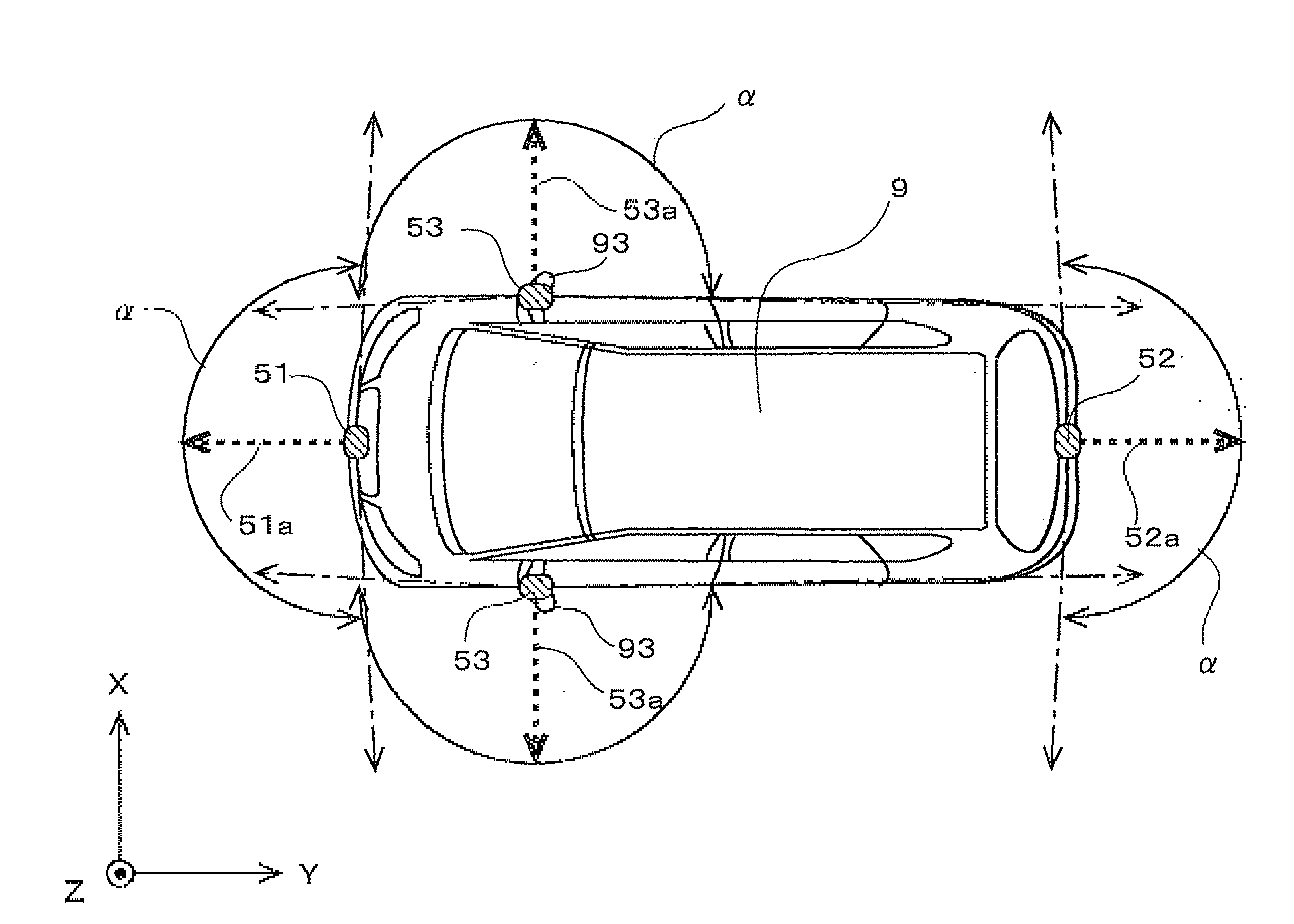
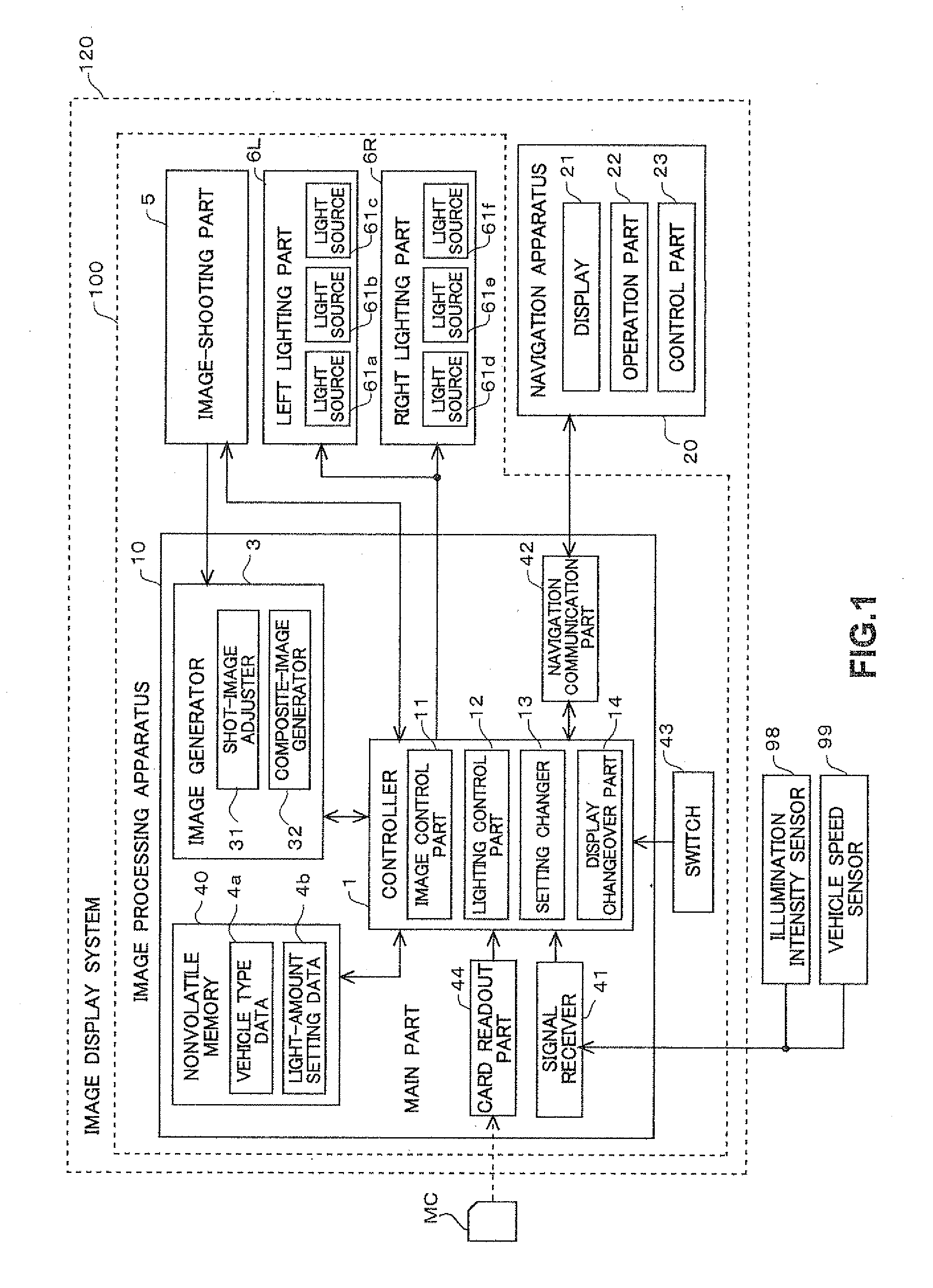
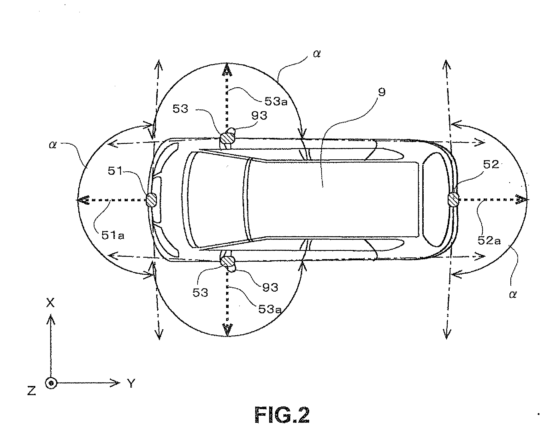
[0050]FIG. 1 is a block diagram showing a configuration of an image display system 120 that is a first embodiment of the invention. The image display system 120 is for installation on a vehicle (a car in this embodiment) and has functions of shooting surroundings of the vehicle, of generating an image and of displaying the image in a cabin of the vehicle. A user (mainly a driver) of the image display system 120 can grasp the surroundings of the vehicle in substantially real time, by using the image display system 120.
[0051]As shown in FIG. 1, the image display system 120 mainly includes an image processing apparatus 100 that generates a vehicle surrounding image showing the surroundings of the vehicle, and a navigation apparatus 20 that displays a variety of information for the user in the vehicle. The vehicle surrounding image generated by the image processing apparatus 100 is displayed on the navigation apparatus 20.
[0052]The navigation ...
second embodiment
2. Second Embodiment
2-1. Outline
[0153]Next, a second embodiment is described. In the first embodiment, a same light-amount parameter is used regardless of the type of the vehicle surrounding image to be displayed. However, in the second embodiment, light-amount parameters according to a type of a vehicle surrounding image are used. A structure and an operational process of an image display system 120 in the second embodiment is almost the same as the structure and the operational process in the first embodiment. Therefore, hereinbelow, a difference between the first and the second embodiments is described.
[0154]FIG. 18 shows an example of light-amount setting data 4b in the second embodiment. As described earlier, six light-amount parameters are provided individually corresponding to a front light source 61a, a center light source 61b and a rear light source 61c of a left lighting part 6L and a front light source 61d, a center light source 61e and a rear light source 61f of a right ...
third embodiment
3. Third Embodiment
[0180]Next, a third embodiment is described. All the light-amount parameters can be changed in the second embodiment. On the other hand, in the third embodiment, a part of the light-amount parameters cannot be changed when a particular type from amongst a plurality of types of the vehicle surrounding image is designated. A structure and an operational process of an image display system 120 in the third embodiment are approximately same as the structure and the operational process of the image display system 120 in the second embodiment. Therefore, hereinbelow, a difference from the second embodiment is described.
[0181]FIG. 26 shows an example of light-amount setting data 4b in the third embodiment. As shown in FIG. 26, the light-amount parameters for rear light sources 61c and 61f are indicated as “fixed at zero” in a parameter set St corresponding to side images P23.
[0182]Rear regions BA (refer to FIG. 4) illuminated by the rear light sources 61c and 61f are not ...
PUM
 Abstract
Description
Claims
Application Information