
Display device comprising multifunction glass, production method, and optical element having a fresnel structure

Active Publication Date: 2012-01-05
TOOZ TECH GMBH
View PDF2 Cites 87 Cited by
  • Summary
  • Abstract
  • Description
  • Claims
  • Application Information

AI Technical Summary

Benefits of technology

[0006]Starting from this, the object of the invention is to improve the display device of the type named at the beginning such that the coupling-in takes place such that disruptive image errors are avoided as far as possible. Furthermore, a production method for a multifunction glass of such a display device is to be provided.
[0008]The coupling-in can thus be carried out such that the image is guided in the multifunction glass to the coupling-out area (for example by total internal reflection). Furthermore, disruptive image errors can be effectively countered by means of the imaging property.
[0016]With this method, a multifunction glass for the display device according to the invention and thus also the display device according to the invention itself can be easily produced.
[0029]In particular, the optically effective surface is a boundary surface of the optical element. This facilitates the production of the optical element. Thus, it can for example be produced by diamond milling. However, it is also possible to produce the optical element by moulding and casting methods.
[0037]With this production method, an optical element with excellent optical properties can be produced.

Problems solved by technology

With display devices according to the type named at the beginning, the problem often arises of coupling the generated image into the multifunction glass such that it is guided in the latter to the coupling-out area without disruptive image errors occurring.

Method used


Image

  • Display device comprising multifunction glass, production method, and optical element having a fresnel structure
  • Display device comprising multifunction glass, production method, and optical element having a fresnel structure
  • Display device comprising multifunction glass, production method, and optical element having a fresnel structure

Examples


Embodiment Construction

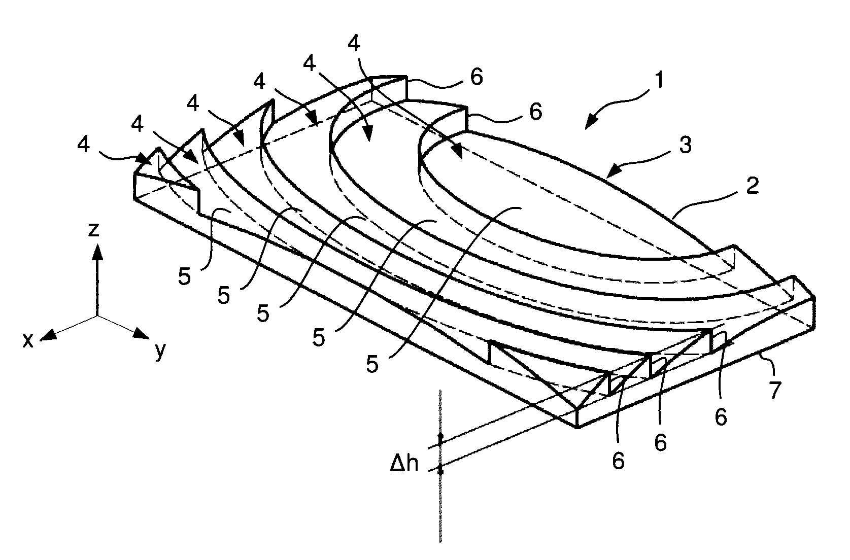
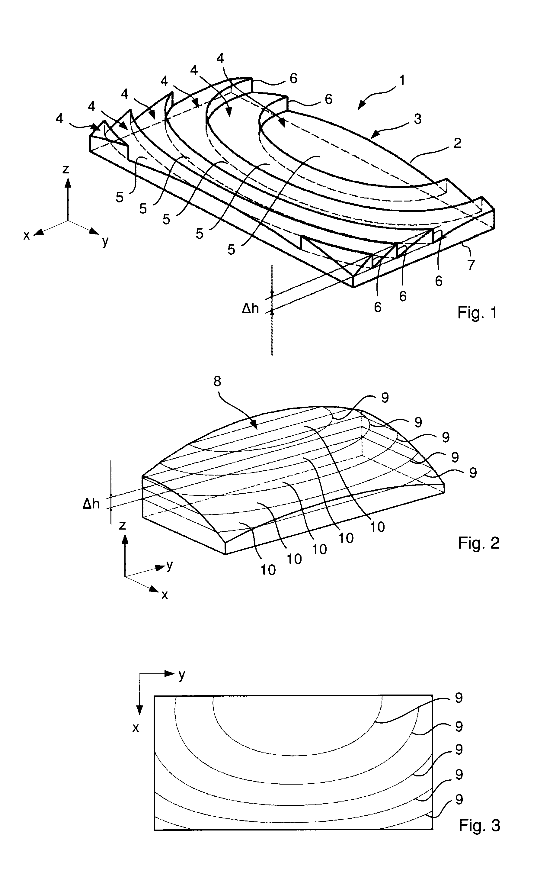
[0081]In the embodiment shown in FIG. 1, the optical element 1 according to the invention, which is here formed as a lens, comprises on its top side 2 a Fresnel structure 3 with several Fresnel segments 4.

[0082]Each Fresnel segment 4 has an optically effective facet 5. In order to achieve the stepped shape shown in FIG. 1, each Fresnel segment 4 normally also comprises an edge 6 which here extends essentially perpendicular to the underside 7 of the optical element 1.

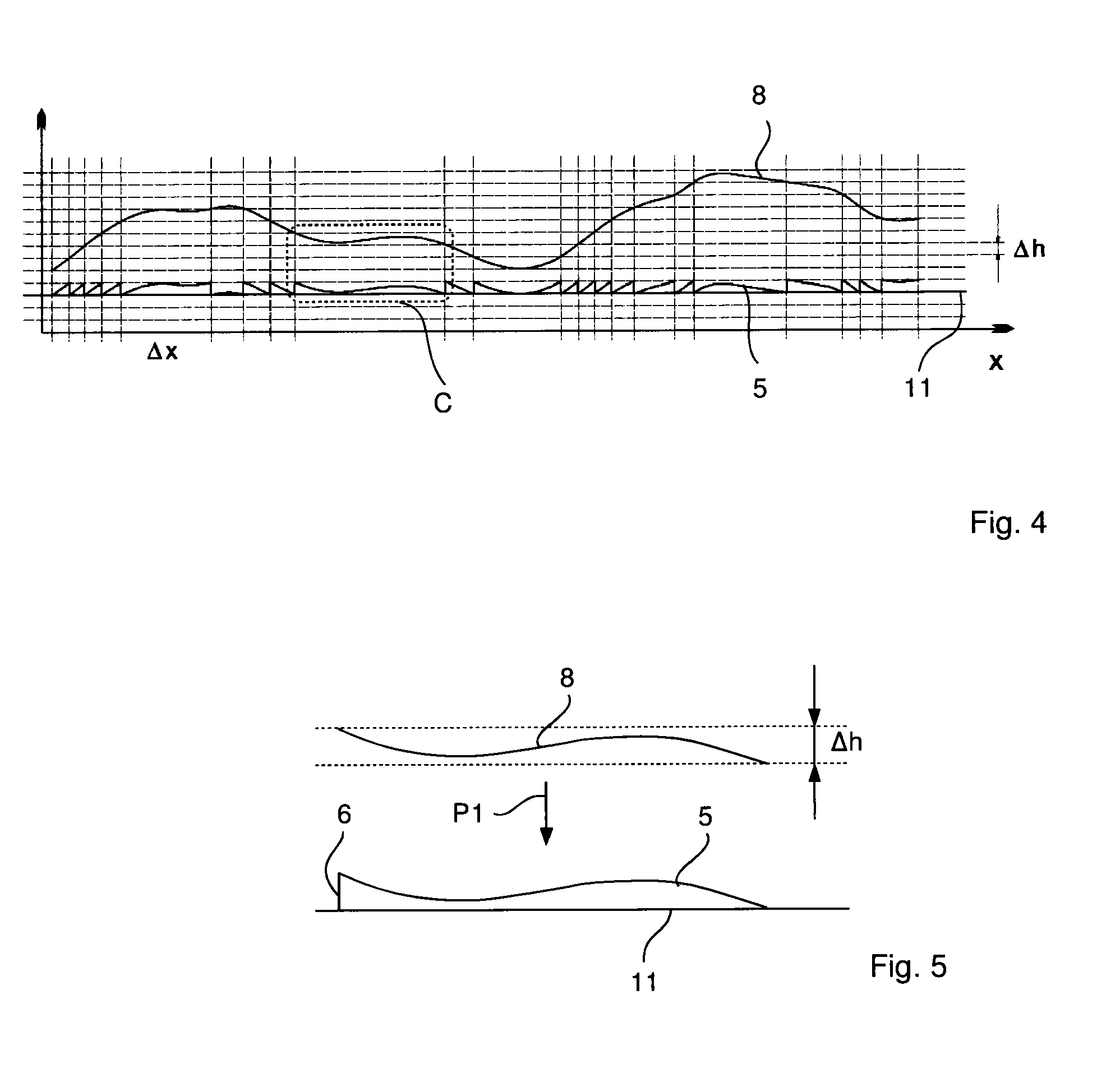
[0083]The common optical action of the facets 5 corresponds to an imaginary optical effective surface 8, such as is shown in FIG. 2, wherein the optical effective surface 8 is curved and has no mirror or rotational symmetry. As can easily be seen from the comparison of FIGS. 1 and 2, the representation in FIG. 2 is rotated by 90° about the z-axis compared with the representation in FIG. 1. The imaginary optical effective surface 8 can be implemented as a Fresnel structure 3 according to FIG. 1 as follows.

[0084]The active...


PUM

PropertyMeasurementUnit
Lengthaaaaaaaaaa
Lengthaaaaaaaaaa
Lengthaaaaaaaaaa

Abstract

A display device including a holding device that can be placed on the head of a user, an image generating module fixed to the holding device and generating an image, and a multifunction glass that is fixed to the holding device and has a coupling in area and a coupling out area. The image produced is coupled into the multifunction glass via the coupling in area, guided in the multifunction glass to the coupling in area, and extracted via the coupling out area, in such a way that the user can perceive the coupled out image superimposed on the surroundings when the holding device is placed on the head of the user. The coupling in area has a Fresnel structure causing a folding of the beam path when the image is injected into the multifunction glass, said structure having an imaging property.

Description

PRIORITY CLAIM[0001]The present application is a National Phase entry of PCT Application No. PCT / EP2010 / 052426, filed Feb. 25, 2010, which claims priority from German Application Number 102009010538.7, filed Feb. 25, 2009, the disclosures of which are hereby incorporated by reference herein in their entirety.FIELD OF THE INVENTION[0002]The present invention relates to a display device including a holding device that can be worn on the head of a user and an image-generating module which generates an image and is attached to the holding device and a method for producing a multifunction glass of such a display device as well as an optical element having an optically effective surface which at least in part has a Fresnel structure with several Fresnel segments.BACKGROUND[0003]An optical element with a Fresnel structure is often used to reduce installation space, for example in the case of illumination lens systems. In this case, e.g. rotationally symmetric Fresnel structures as well as ...

Claims


Application Information

Patent Timeline
IPC IPC(8): G02B27/01B24B51/00B24B1/00C03B11/08C03C19/00
CPCG02B3/08G02B27/0172G02B27/017
Inventor DOBSCHAL, HANS-JUERGENRUDOLPH, GUENTERLINDIG, KARSTEN
Owner TOOZ TECH GMBH
Learn More