Card reader and control method of card reader

a card reader and control method technology, applied in the field of card readers, can solve the problems of large leakage of magnetic data on the magnetic stripe, and inability to analyze the output signal of the pre-head, so as to reduce the cost reduce the size of the magnetic head, and ensure the accuracy of the magnetic information

Active Publication Date: 2012-01-05
SANKYO SEIKI MFG CO LTD
View PDF12 Cites 28 Cited by
  • Summary
  • Abstract
  • Description
  • Claims
  • Application Information

AI Technical Summary

Benefits of technology

[0009]The present invention is devised considering such a problem, and the first objective is to provide a card reader capable of preventing the illegal acquisition of magnetic data recorded on a magnetic stripe based on the output signal from the pre-head.
[0047]Also, in the card reader of the present invention, the illegal acquisition of the magnetic information on the card can be prevented, and minimization of the size and cost reduction is possible. Further, by using the card reader control method of the present invention, the illegal acquisition of the magnetic information on the card can be prevented, and the card reader can be minimized in size and manufactured at lower cost.

Problems solved by technology

However, in the card reader disclosed in JP 2002-74607, when a lead wire is illegally attached to an output terminal of the pre-head or to a cable or the like linking the pre-head and the circuit board, there is a risk that the output signal from the pre-head could be analyzed and therefore, the magnetic data recorded on the magnetic stripe may be leaked (stolen).
However, since the demodulation circuit and the encryption circuit are stored inside the case of the magnetic head in this card reader, the size of the magnetic head has to be large.
Therefore, in the card reader disclosed in JP 2002-189987, it is difficult to minimize the size of the card reader.
Also, the magnetic head in which the demodulation circuit and the encryption circuit are stored inside the case is expensive; therefore, the card reader disclosed in JP 2002-189987 increases the cost of the card reader.

Method used


Image

  • Card reader and control method of card reader
  • Card reader and control method of card reader
  • Card reader and control method of card reader

Examples


first embodiment

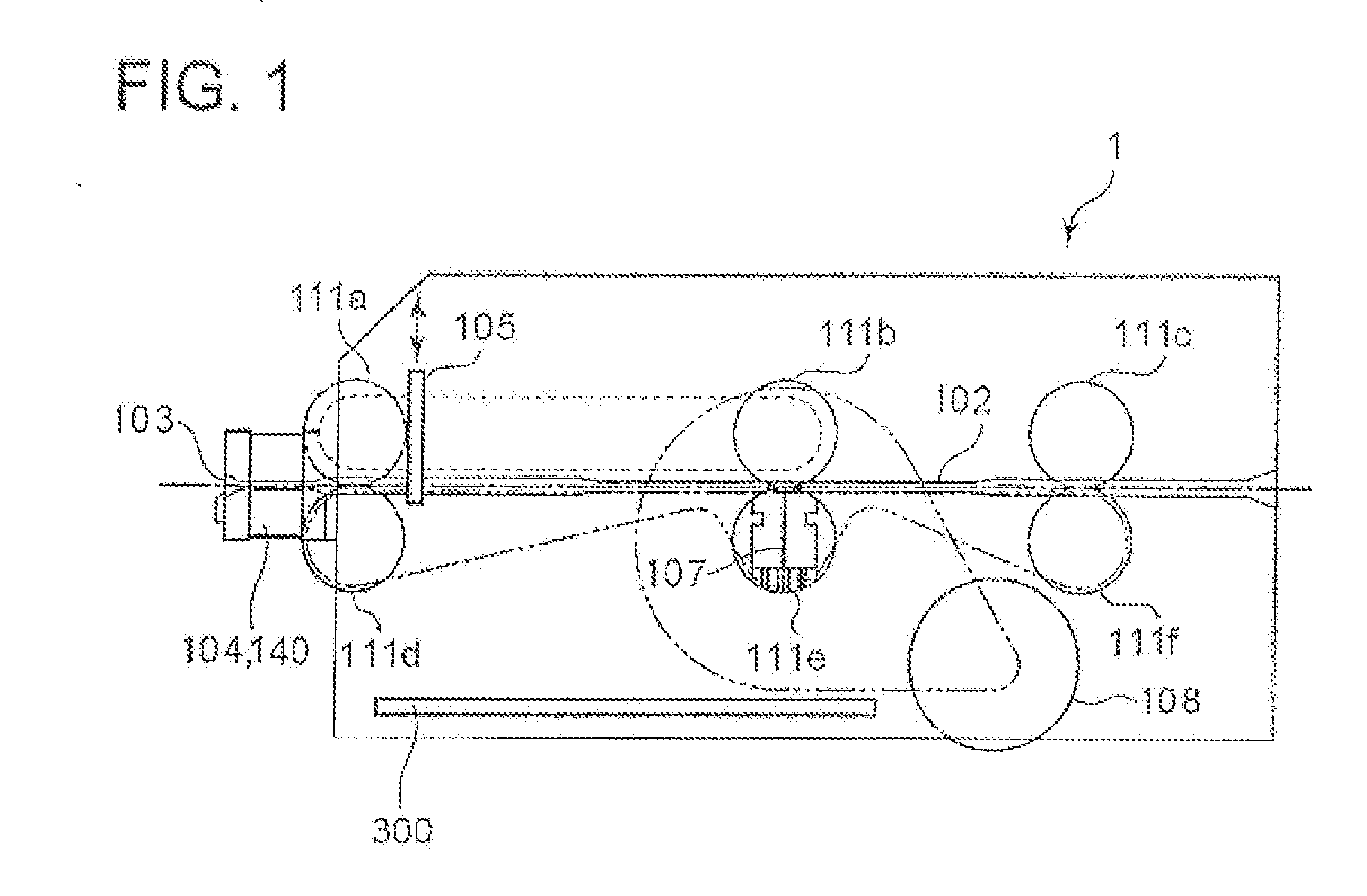
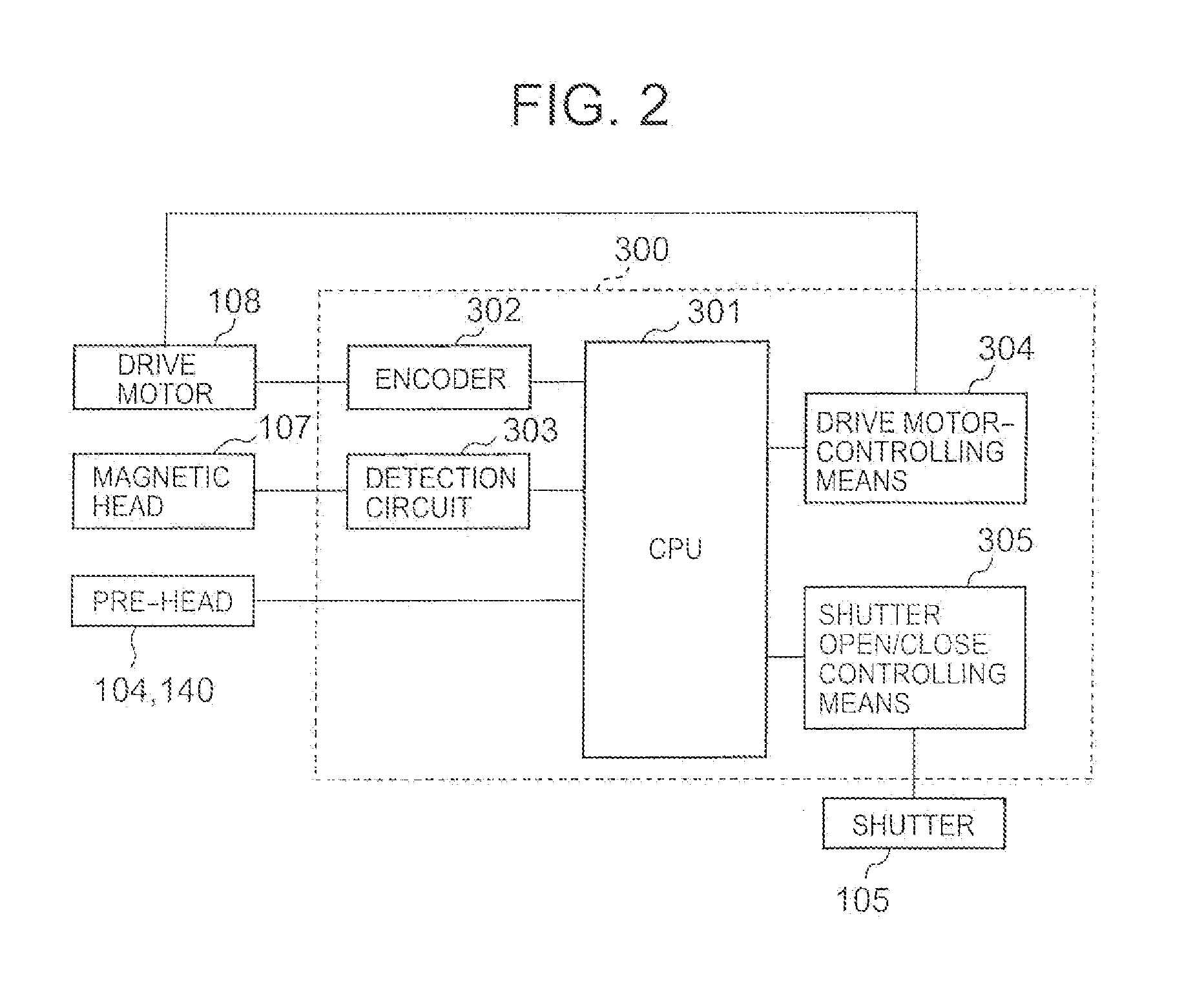
[0067]FIG. 1 is a vertical cross-section of the structure of a card reader 101 of the first embodiment of the present invention. FIG. 2 is a block diagram showing the electrical configuration of the card reader 101 of the first embodiment of the present invention.

[0068]In FIG. 1, the card reader 101 of the first embodiment of the present invention comprises a card insertion slot 103 for guiding magnetic cards to a transport passage 102, a pre-head for sending signals which are the sign to drive a drive motor 108 (described later) and sending signals which are the sign to open / close a shutter 105 to the transport passage 102, a magnetic head 107 for sending / receiving the magnetic data to / from the magnetic card when the inserted card is a magnetic card, a drive motor 108 for driving drive rollers 111d-111f via a transmitting belt or a drive shaft, driven rollers 111a-111c, respectively paired with the drive rollers 111d-111f, for holding the inserted cards, a circuit board 300, and ot...

second embodiment

[0096]Configuration of Card Reader:

[0097]FIG. 8 is a plan view to explain the configuration of a major portion of a card reader 1 of the second embodiment of the present invention.

[0098]A card reader 1 of the second embodiment is a device for reading magnetic data recorded on a card 2 and writing magnetic data on the card 2. This card reader 1 is equipped with, as shown in FIG. 8, a card processing portion 3 for reading magnetic data recorded on the card 2 and writing magnetic data on the card 2 and a card inserting portion 5 at which a card insertion slot 4 is formed for the card be inserted and discharged. Formed inside the card reader 1 is a card transport passage 6 on which the card 2 inserted from the card insertion slot 4 is transported.

[0099]In the second embodiment; the card 2 is transported in the X direction (the left-right direction) of FIG. 8. In other words, the X direction is the transporting direction of the card 2. Also, the Z direction (the direction perpendicular t...

modification example 1

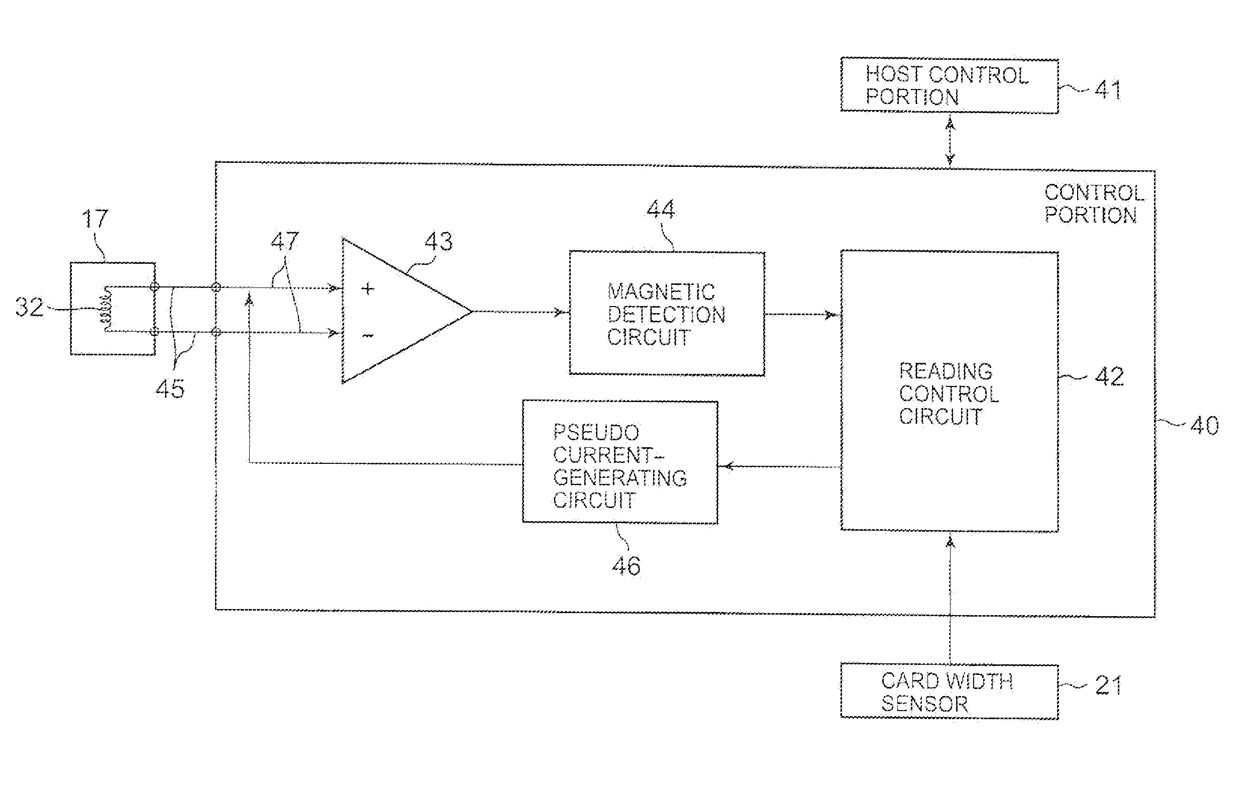
[0141]FIG. 14 is a block diagram of the configuration of the control portion 40 and its related portions of a modification example 1 of the second embodiment of the present invention. Note that, in FIG. 14, only the configuration of the control portion 40 related to the control of the magnetic head 9 is illustrated.

[0142]In the above-described second embodiment, the pseudo current is generated to the reading-side coil 32 except for the period of time when the pre-head 17 is reading the magnetic data. Beside this, the pseudo current may be generated to the reading-side coil 27 except for the period of time when the magnetic head 9 is reading the magnetic data, for example. The configuration of the control portion 40 and an example of the control of the magnetic head 9 in this case are described hereinafter.

[0143]The control portion 40 is equipped with a writing control circuit 51 and a reading control circuit 52 as the components related to the control of the magnetic head 9. The wri...


PUM

PropertyMeasurementUnit
thicknessaaaaaaaaaa
magnetic gapaaaaaaaaaa
magneticaaaaaaaaaa

Abstract

The present invention is to provide a card reader that can prevent the illegal acquisition of magnetic information recorded on a magnetic stripe, based on an output signal from a pre-head. More specifically described, in a card reader having a card insertion slot for guiding a magnetic card having a magnetic stripe to a transport passage and a pre-head arranged in the vicinity of the card insertion slot for detecting the presence of the magnetic stripe, the pre-head is equipped with a head portion having at least one pair of magnetic cores arranged to be opposite from each other having a magnetic gap between them and coils wound around a pair of the magnetic cores; and a signal different from that of the magnetic information recorded on the magnetic stripe is output from the pre-head.

Description

[0001]The present application claims priority from PCT Patent Application No. PCT / JP2010 / 001433 filed on Mar. 3, 2010, which claims priority from Japanese Patent Application Nos. JP 2009-052733 filed on Mar. 5, 2009, and JP 2009-223073 filed on Sep. 28, 2009, the disclosures of which is incorporated herein by reference in its entirety.FIELD OF THE INVENTION[0002]The present invention relates to a card reader that reads magnetic data recorded on cards and to its control method.DESCRIPTION OF RELATED ART[0003]A card reader having a pre-head that detects the presence of a magnetic stripe is used in the following manner, for example. The card conventionally used in financial institutions such as banks to realize cashless transactions and ID verification is a magnetic card having a magnetic stripe formed on a surface of a plastic substrate. Magnetic data is recorded / reproduced by a card reader device (including a card reader / writer). More specifically described, the card reader takes a m...

Claims


Application Information

Patent Timeline
Patent Type & Authority Applications(United States)
IPC IPC(8): G11B25/04
CPCG06K7/084G06K13/08G06K13/0875G06K7/082G11B5/00808
Inventor MIYABE, TAKAAKIKOMATSU, YOSHIHITOISHIKAWA, KAZUTOSHIHIGASHI, KATSUHISA
Owner SANKYO SEIKI MFG CO LTD
Why Eureka
Try Eureka