Connection of a prosthesis structure with an implant structure

a technology of prosthesis structure and implant structure, which is applied in the field of connection devices, can solve the problems of high consumption of retention parts, difficulty and labor, and irregularly not being able to place implant structures exactly at the desired target, and achieves the effects of convenient, comfortable and reliable placement or snapping, and relatively easy replacemen

Inactive Publication Date: 2012-01-05
FORUM IMMOBILIEN
View PDF16 Cites 19 Cited by
  • Summary
  • Abstract
  • Description
  • Claims
  • Application Information

AI Technical Summary

Benefits of technology

[0011]In that the adjacent outer surface of the retention rim and inner surface of the holding rim are at least partly not contacting each other but are spaced from each other when essentially no radial forces are acting on the holding rim of the holding shell and on the retention rim of the retention insert, it can, i.a., be achieved that the retention insert is connected relatively loosely with the holding shell when the connection device has not yet been placed on the implant structure. Advantageously, this loose connection is just sufficient for holding the retention insert in the holding shell to thus allow a comfortable handling. This loose connection can allow the retention insert to be relatively easily removed from and inserted in the holding shell without having to be substantially deformed or strained in any other way. Thus, it is possible to insert and remove the retention insert gently, which can improve the flexibility and lifetime of the connection device.
[0028]A further different aspect of the invention relates to a demounting tool for demounting a retention insert from a holding shell of a connection device as described above. The demounting tool comprises a sleeve-shaped head which can be arranged between an outer surface of a retention rim of the retention insert and an inner surface of a holding rim of the holding shell when the retention insert is arranged in a retainer of the holding shell. An inner side of the head is conical so that the retention rim of the retention insert is moved in the direction of a central axis of the connection device when the head of the demounting tool is arranged between the outer surface of the retention rim of the retention insert and the inner surface of the holding rim of the holding shell. By means of such a demounting tool, the retention rim can be moved inwardly or in the direction of the central axis in such a resilient manner that the retention insert is no longer held in the holding shell and thus can be removed from the retention shell without difficulty. In particular, a projection of the retention insert can be moved essentially completely out of a groove of the holding shell so that the retention insert is no longer connected with the holding shell. Preferably, a distal end of the head of the demounting tool has a tapered shape. Such a tapered shape of the head allows the head to be centered and inserted easily between the retention rim and the holding rim.

Problems solved by technology

A problem nowadays often occurring in artificial dentures is the fact that the position of the dental implant or the implant structure depends on various factors, for example the condition of the jaw bone, the progress of a possible osseointegration and in particular also an exact insertion.
Accordingly, nowadays it is regularly not possible to place implant structures exactly at a desired target place and in a desired target position and connect them with the prosthesis structure.
For such a selection and adaptation of the retention parts during fitting of the prosthesis structure, however, it is often necessary to test different hardnesses of retention parts, which can be difficult and laborious.
Moreover, when being mounted in and dismounted from the corresponding caps, the retention parts are also squeezed and damaged due to the mentioned deformation, which can lead to a high consumption of retention parts.
Moreover, during everyday use of the prosthesis structure and as a consequence of the mentioned compensation function, the retention bodies are strained so much by deformation as well as a non-uniform mounting and dismounting of the prosthesis structure that they have to be renewed regularly, which can be laborious and expensive.
Finally, dirt particles can collect in the hollow spaces formed by the deformation of the retention parts, which is mostly not desired.

Method used


Image

  • Connection of a prosthesis structure with an implant structure
  • Connection of a prosthesis structure with an implant structure
  • Connection of a prosthesis structure with an implant structure

Examples


first embodiment

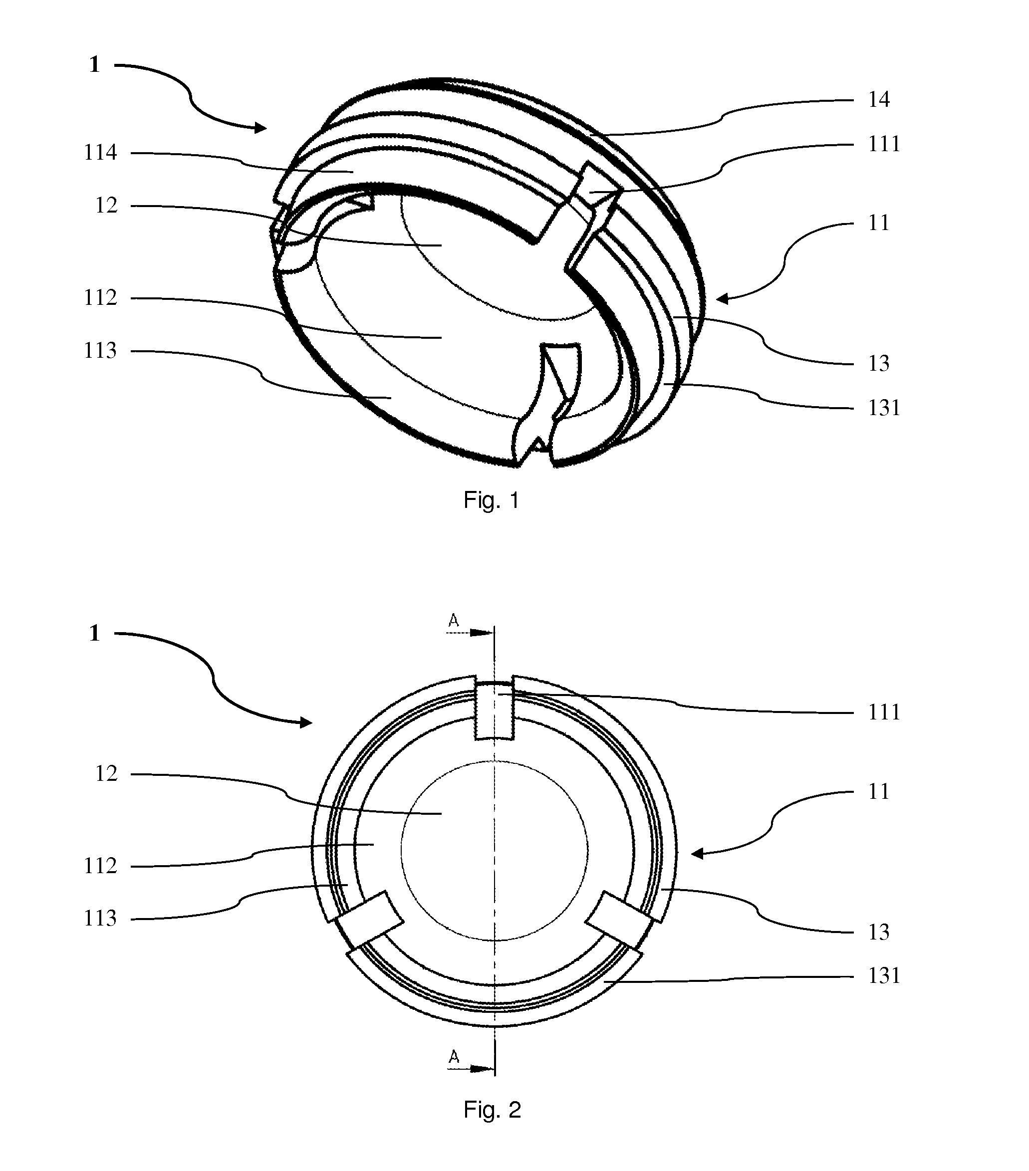
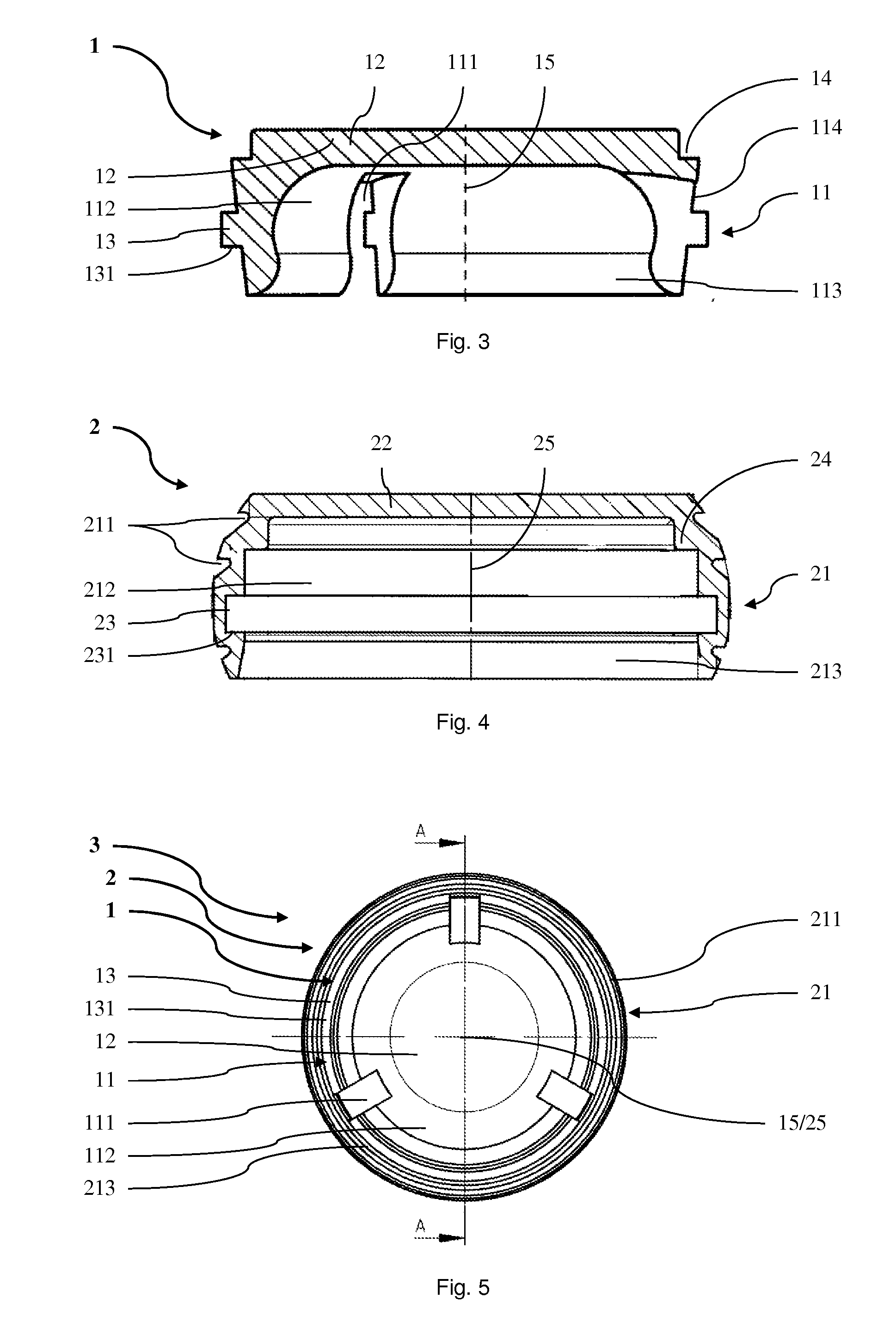
[0041]FIG. 1 shows a retention insert 1 according to the invention. The substantially cup-shaped retention insert 1 comprises a substantially disk-shaped closed end side 12 and a substantially ring-shaped retention rim 11 projecting at the circumference thereof at an angle. The retention rim 11 comprises an outer surface 114, three recesses 111 uniformly spaced from each other in the circumferential direction, and lamella portions 112 arranged therebetween. The recesses 111 start from an end of the retention rim 11 facing away from the end side 12 and extend in the direction of the end side 12 over more than 80% of the retention rim 11. The lamella portions 112 comprise an inner surface describing an inner surface of the retention rim 11 opposite to the outer surface 114. The inner surfaces of the lamella portions 112 are rounded outwardly towards the open end of the retention insert 1, i.e. towards the end of the retention insert 1 facing away from the end side 12, and thus compris...

second embodiment

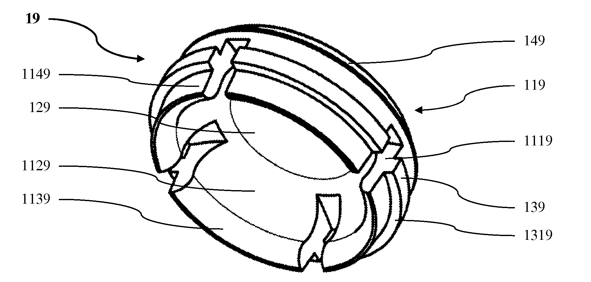
[0053]FIG. 8 shows a retention insert 19 according to the invention, which retention insert is designed substantially analogously to the retention insert 1 described above, except for the fact that it comprises a retention rim 119 having four recesses 1119. In particular, the retention insert 19 comprises an end side 129 as well as the retention rim 119 with an outer surface 1149, the four recesses 1119 spaced uniformly with respect to each other in the circumferential direction, as well as lamella portions 1129 arranged therebetween. The recesses 1119 are angled about 90° relative to each other. They start from an end of the retention rim 119 facing away from the end side 129 and extend in the direction of the end side 129 over more than 80% of the retention rim 119. The inner surfaces of the lamella portions 1129 have a curved portion 1139. The retention insert 19 further comprises a step 149 and a projection 139 having a projection supporting surface 1319. The retention insert 19...

third embodiment

[0054]FIG. 9 shows a retention insert 18 according to the invention, which retention insert is designed substantially analogously to the retention inserts 1 and 19 described above, except for the fact that it comprises a retention rim 118 having six recesses 1118. In particular, the retention insert 18 comprises an end side 128 as well as the retention rim 118 with an outer surface 1148, the six recesses 1118 spaced uniformly with respect to each other in the circumferential direction, as well as lamella portions 1128 arranged therebetween. The recesses 1118 are angled about 60° relative to each other. They start from an end of the retention rim 118 facing away from the end side 128 and extend in the direction of the end side 128 over more than 80% of the retention rim 118. The inner surfaces of the lamella portions 1128 have a curved portion 1138. The retention insert 18 further comprises a step 148 and a projection 138 having a projection supporting surface 1318. The retention ins...


PUM


Abstract

A connection device for connecting a prosthesis structure with an implant structure comprises a holding shell and a retention insert. The retention insert comprises an end side and a substantially ring-shaped retention rim projecting therefrom. The holding shell comprises an end side and a substantially ring-shaped holding rim projecting therefrom. The holding rim and the end side of the holding shell form a retainer in which the retention insert can be arranged such that an outer surface of the retention rim is adjacent to an inner surface of the holding rim. Moreover, the outer surface of the retention rim is at least partly spaced from and adjacent to the inner surface of the holding rim when the retention insert is arranged in the retainer of the holding shell and when essentially no radial forces are acting on the holding rim and on the retention rim. In that the adjacent outer surface of the retention rim and inner surface of the holding rim are at least partly not contacting each other but are spaced from each other when essentially no radial forces are acting on the holding rim and on the retention rim, it can, i.a., be achieved that the retention insert is connected relatively loosely with the holding shell when the connection device has not yet been placed on the implant structure. This loose connection can allow the retention insert to be relatively easily removed from the holding shell and inserted in the holding shell without having to be substantially deformed or strained in any other way. Thus, it is possible to insert and remove the retention insert gently, which can improve the flexibility and lifetime of the connection device.

Description

CROSS-REFERENCE TO RELATED APPLICATIONS[0001]This application claims priority from European application EP 10 16 8364.7, filed Jul. 2, 2010, which is incorporated herein by reference in its entirety.FIELD OF THE INVENTION[0002]The invention relates to a connection device as well to a corresponding retention insert, a corresponding method and a corresponding demounting tool. Connection devices of this kind, which comprise a holding shell and a retention insert, wherein the holding shell has an end side and a substantially ring-shaped holding rim projecting therefrom and the retention insert has an end side and a substantially ring-shaped retention rim projecting therefrom, and wherein the holding rim and the end side of the holding shell form a retainer in which the retention insert can be arranged such that an outer surface of the retention rim of the retention insert is located adjacent to an inner surface of the holding rim of the holding shell, can be used for connecting a dental...

Claims


Application Information

Patent Timeline
Patent Type & Authority Applications(United States)
IPC IPC(8): A61C8/00A61C13/225A61C13/12A61C5/35A61C5/70
CPCA61C8/0048A61C8/0089A61C13/2656A61C8/0062B25B27/00A61C8/0016A61C8/005A61C13/12A61C5/08A61C8/00A61C8/0057A61C8/0093A61C13/267A61C5/70A61C5/35
Inventor FISCHLER, ELISABETHFISCHLER, TITUSBAECHLER, MARTINBAECHLER, JUERGSCHAFFNER, ROLAND
Owner FORUM IMMOBILIEN
Why Eureka
Try Eureka