Breaking trapping sets using targeted bit adjustment

Inactive Publication Date: 2012-01-05
AVAGO TECH WIRELESS IP SINGAPORE PTE
View PDF10 Cites 87 Cited by
  • Summary
  • Abstract
  • Description
  • Claims
  • Application Information

AI Technical Summary

Problems solved by technology

Trapping sets, which represent subgraphs in a Tanner graph of an LDPC code, typically have a strong influence on error-floor characteristics of the LDPC code because a trapping set may force the decoder to converge to an incorrect result.

Method used


Image

  • Breaking trapping sets using targeted bit adjustment
  • Breaking trapping sets using targeted bit adjustment
  • Breaking trapping sets using targeted bit adjustment

Examples


Embodiment Construction

[0042]Reference herein to “one embodiment” or “an embodiment” means that a particular feature, structure, or characteristic described in connection with the embodiment can be included in at least one embodiment of the invention. The appearances of the phrase “in one embodiment” in various places in the specification are not necessarily all referring to the same embodiment, nor are separate or alternative embodiments necessarily mutually exclusive of other embodiments. The same applies to the term “implementation.”

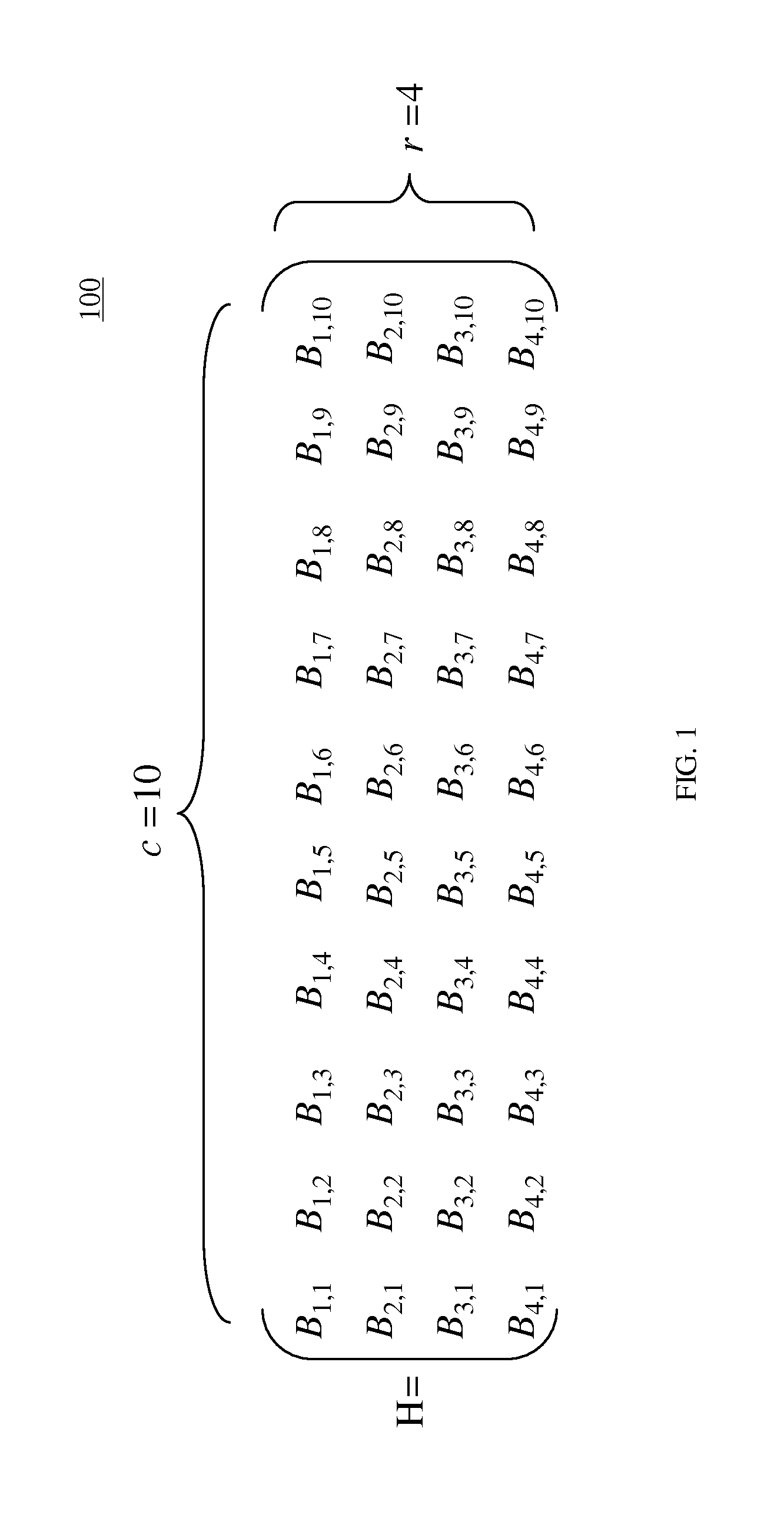
[0043]FIG. 1 shows one implementation of a parity-check matrix 100 that may be used to implement a regular, quasi-cyclic (QC) LDPC code. Parity-check matrix 100, commonly referred to as an H-matrix, comprises 40 circulants Bj,k that are arranged in r=4 rows of circulants (i.e., block rows) where j=1, . . . , r and c=10 columns of circulants (i.e., block columns) where k=1, . . . , c. A circulant is a sub-matrix that is either an identity matrix or is obtained by cyclically ...


PUM


Abstract

In one embodiment, an LDPC decoder performs a targeted bit adjustment method to recover a valid codeword after the decoder has failed. In a first stage, a post processor initializes the decoder by saturating LLR values output by the decoder during the last (i.e., failed) iteration to a relatively small value. Then, two-bit trials are performed, wherein LLR values corresponding to two bits of the codeword are adjusted in each trial. Decoding is performed with the adjusted values, and if the number of unsatisfied check nodes exceeds a specified threshold, then a second stage is performed. The post processor initializes the decoder by saturating the LLR values output by the decoder during the last (i.e., failed) iteration of the first stage to a relatively small value. The second stage then performs single-bit adjustment trials, wherein one LLR value corresponding to one bit of the codeword is adjusted in each trial.

Description

CROSS-REFERENCE TO RELATED APPLICATIONS[0001]The subject matter of this application is related to:[0002]U.S. patent application Ser. No. 12 / 113,729 filed May 1, 2008,[0003]U.S. patent application Ser. No. 12 / 113,755 filed May 1, 2008,[0004]U.S. patent application Ser. No. 12 / 323,626 filed Nov. 26, 2008,[0005]U.S. patent application Ser. No. 12 / 401,116 filed Mar. 10, 2009,[0006]U.S. patent application Ser. No. 12 / 675,981 filed on Mar. 2, 2010,[0007]U.S. patent application Ser. No. 12 / 677,322 filed Mar. 10, 2010,[0008]U.S. patent application Ser. No. 12 / 680,810 filed Mar. 30, 2010,[0009]U.S. application Ser. No. 12 / 524,418 filed on Jul. 24, 2009,[0010]U.S. patent application Ser. No. 12 / 420,535 filed Apr. 8, 2009,[0011]U.S. patent application Ser. No. 12 / 475,786 filed Jun. 1, 2009,[0012]U.S. patent application Ser. No. 12 / 260,608 filed on Oct. 29, 2008,[0013]PCT patent application no. PCT / US09 / 41215 filed on Apr. 21, 2009,[0014]U.S. patent application Ser. No. 12 / 427,786 filed on Apr....

Claims


Application Information

Patent Timeline
Patent Type & Authority Applications(United States)
IPC IPC(8): H03M13/05G06F11/10
CPCH03M13/09H03M13/1108H03M13/1111H03M13/1128H03M13/1142H03M13/6591H03M13/3723H03M13/373H03M13/451H03M13/6306H03M13/3707
Inventor GUNNAM, KIRAN
Owner AVAGO TECH WIRELESS IP SINGAPORE PTE
Why Eureka
Try Eureka