Revolving Door

a technology of revolving doors and hinges, which is applied in the direction of doors/window applications, doors/window fittings, turnstiles, etc., can solve the problems of high canopy structure, unfavorable visual appearance, and large space requirements above or below the turnstile, and achieve the effect of reducing the shortfall of the state-of-the-ar

Inactive Publication Date: 2012-01-12
DORMA GMBH & CO KG
View PDF31 Cites 15 Cited by
  • Summary
  • Abstract
  • Description
  • Claims
  • Application Information

AI Technical Summary

Benefits of technology

[0006]An object of the invention is to reduce the shortfalls of the state-of-the-art.

Problems solved by technology

Due to the immense torque that the drive needs to apply for rotating the turnstile of such a door, the drive motors are relatively large dimensioned that results in enormous space requirements above or below the turnstile.
Therefore, most of the time, the revolving door drives are installed above the turnstile, resulting in a visually unfavorable, high canopy structure.

Method used


Image

  • Revolving Door
  • Revolving Door
  • Revolving Door

Examples


first embodiment

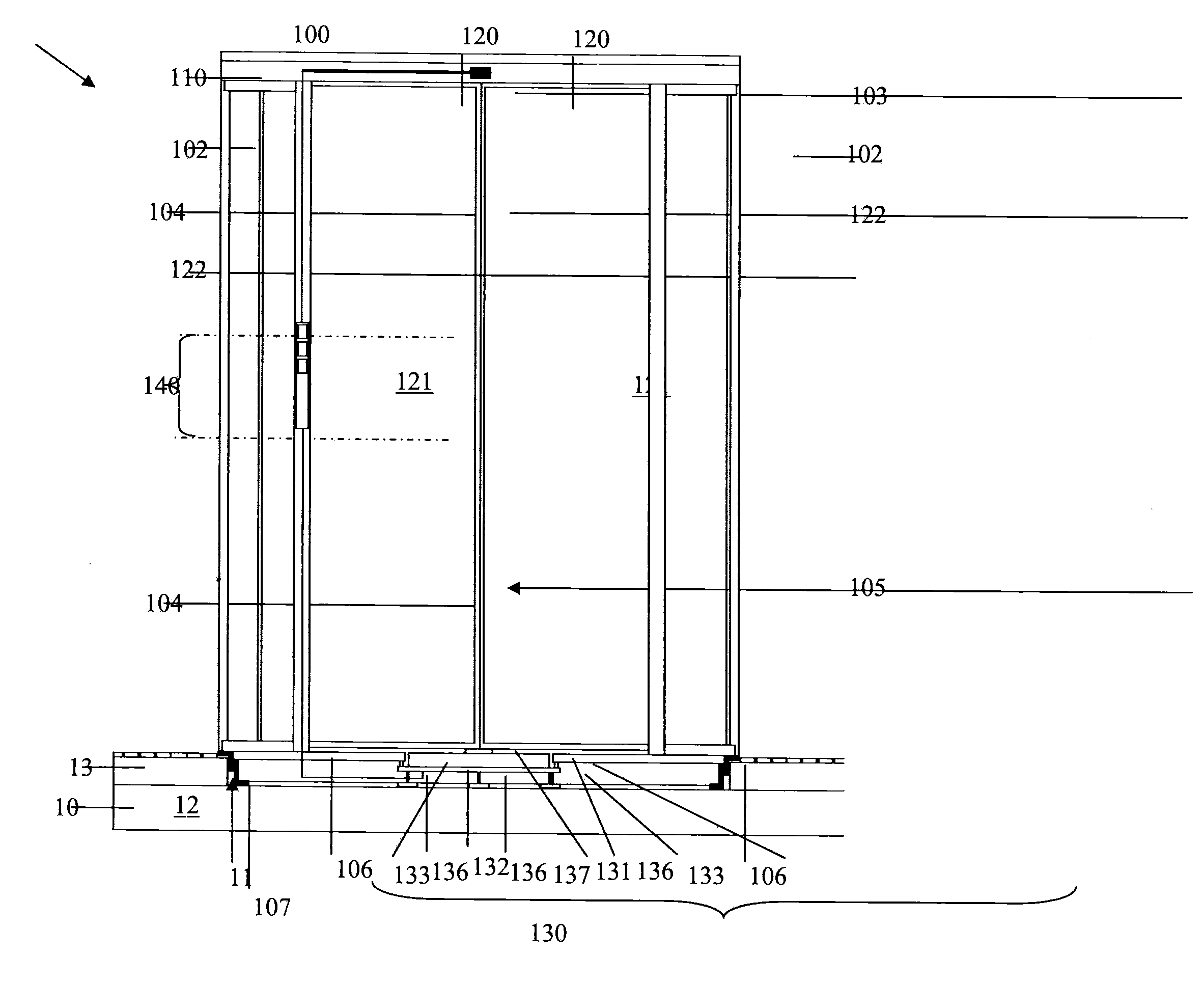
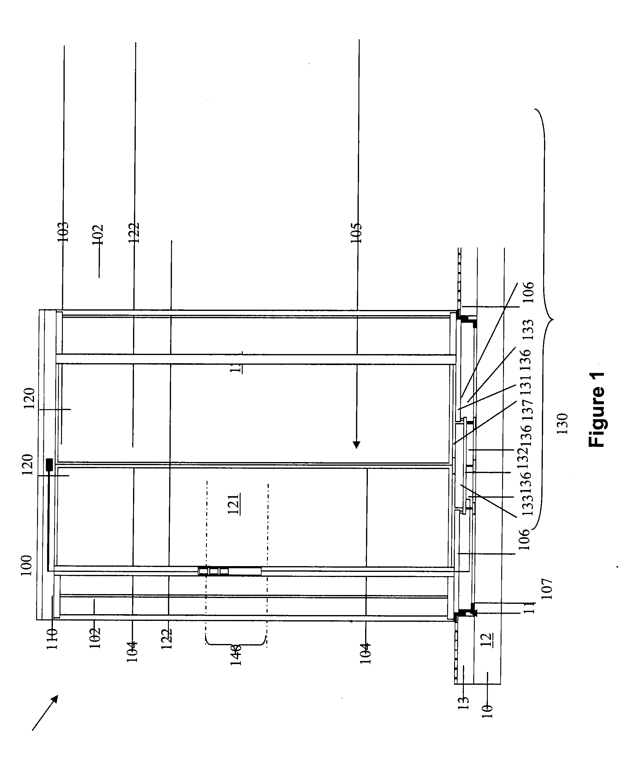
[0019]FIG. 1 shows a revolving door 100 according to the invention. The revolving door 100 is conceived to be free standing. This means, it is incorporated as an autonomous component into a non-illustrated building. The revolving door 100 comprises a turnstile formed by a rotating column 105, to which several revolving leaves 120 are attached in a known manner. By way of example, the revolving leaves 120 are configured as glass door leaves, which respectively comprise a frame profile 122, in which a respective glass panel 121 is inserted. The rotating column 105, with the stationarily attached revolving leaves 120, is placed onto a drive 130 and accommodated to be freely rotational in the revolving door 100. The drive 130 is countersunk in a floor 10 of the building.

[0020]Essentially, the floor 10 comprises an unfinished floor 12 and a cover layer 13, in which a reception space, respectively a reception 11 is configured for the drive 130. In the present illustrated embodiment the co...

third embodiment

[0032]FIG. 5 shows a revolving door 100 according to the invention. With regard to the revolving leaves 120, respectively the turnstile, the revolving door 100 is configured like the previous embodiments. The revolving door thus has a canopy 110 with a ring-shaped canopy frame 111. In addition, on both sides, the revolving door 100 is encased by two posts 101, which are preferably disposed in the respective centre of the respectively adjoining drum wall 102. The drive 130 is again disposed on the underside. The posts 101 and the cross member 112 separate the panels 1 of the glass façade from each other.

[0033]The invention is not limited to the previous embodiments. The canopy structure 110 may have a different configuration. For example the cross member 112 can be foregone. In addition, the ring-shaped canopy frame 111 itself may be foregone, as long as the turnstile is accommodated to freely rotate at its upper end, for example in a ceiling of the room or the like. In this case, th...


PUM


Abstract

A revolving door that has a drive, which is operatively connected to a turnstile of the revolving door and rotationally drives the turnstile. The drive includes a drive motor configured as a multipole electro-motor, the axis of rotation thereof extending parallel or coaxially to the axis of rotation of the turnstile and has a height of equal to or smaller than 80 mm.

Description

BACKGROUND OF THE INVENTION[0001]1. Field of the Invention[0002]The invention relates to an automated revolving door that is provided with a motor drive.[0003]2. Description of the Related Art[0004]A revolving door system is known from EP 2 072 737 A2, which has a motor drive in a canopy structure above the turnstile of the revolving door system. The turnstile is formed by a rotating column with the revolving door leaves attached thereto. A drive motor is operatively connected to the rotating column via an output shaft and a reversing gear. The output shaft extends approximately vertically to the longitudinal extension of the rotating column.[0005]Due to the immense torque that the drive needs to apply for rotating the turnstile of such a door, the drive motors are relatively large dimensioned that results in enormous space requirements above or below the turnstile. Therefore, most of the time, the revolving door drives are installed above the turnstile, resulting in a visually unfa...

Claims


Application Information

Patent Timeline
Patent Type & Authority Applications(United States)
IPC IPC(8): E06B5/00E05F15/10
CPCE05Y2900/10E05Y2600/10E05F15/608E05Y2800/264E05Y2600/452E05F15/106
Inventor BUSCH, SVENGLANZ, MICHAELSCHMITZ, THOMAS
Owner DORMA GMBH & CO KG
Why Eureka
Try Eureka