

Working Vessel Including a Removable Collar and Electric Household Appliance for Culinary Preparation Equipped with Such a Vessel
- Summary
- Abstract
- Description
- Claims
- Application Information
AI Technical Summary
Benefits of technology
Problems solved by technology
Method used
Image

Examples
Embodiment Construction
[0025]Only the elements necessary for the understanding of the invention have been shown. To make the drawings easier to read, the same elements have the same reference numbers from one figure to another.
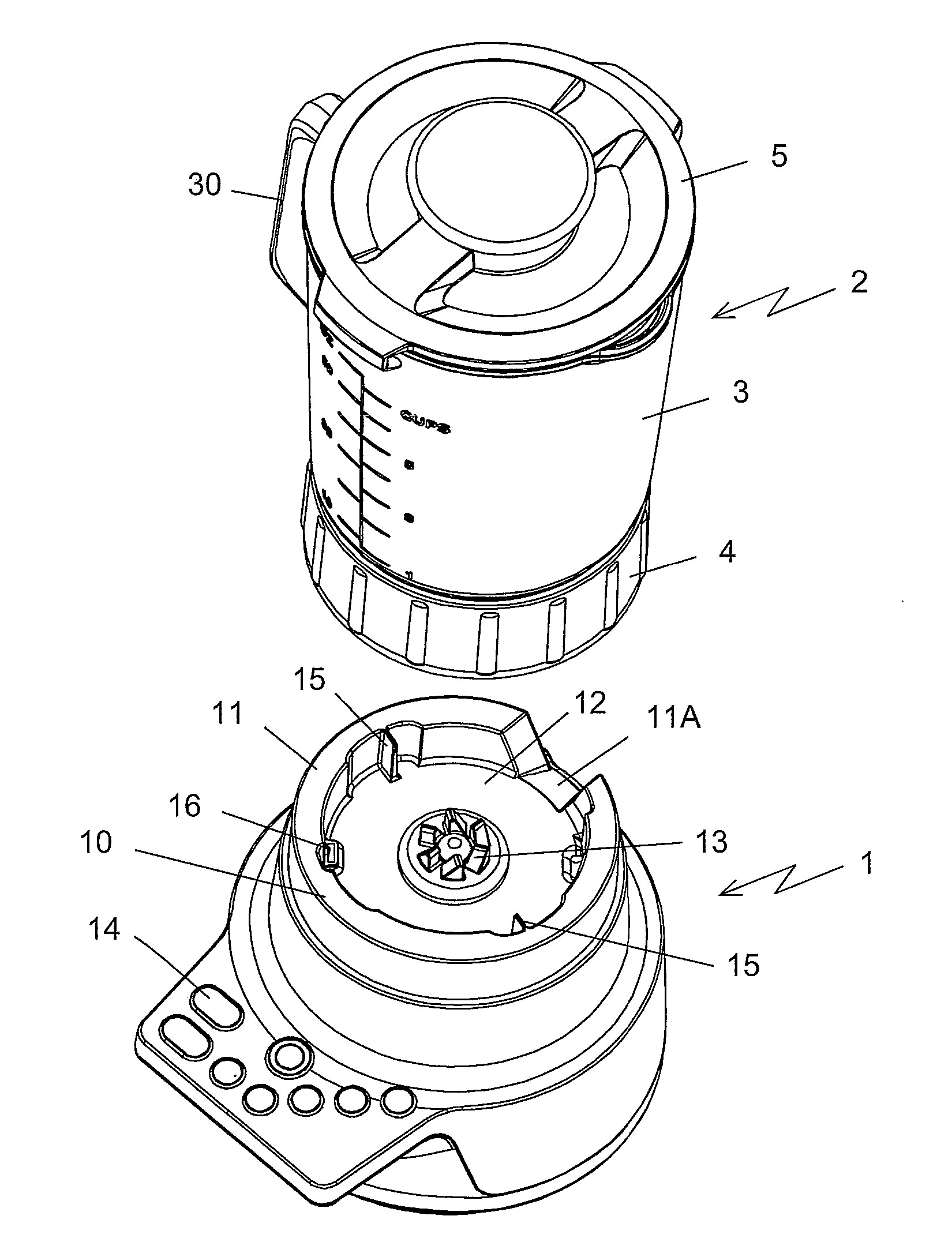
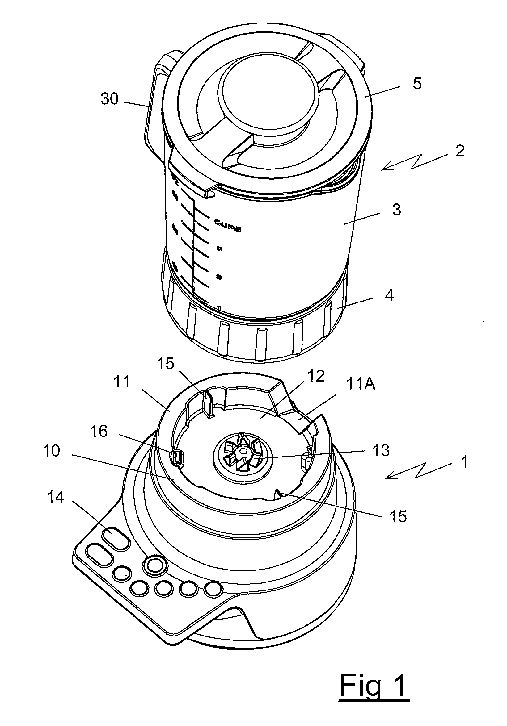
[0026]FIG. 1 shows an electric household appliance for culinary preparation of the invention including a motor housing 1 and a working vessel 2 equipped with a lid 5, the working vessel 2 comprising a casing 3 equipped with a handle and a removable collar 4 designed to be positioned on a receiving base 10 of the motor housing 1 by a simple vertical translation movement.
[0027]The receiving base 10 includes a peripheral ring 11 cooperating with the collar 4 for ensuring the centering of the working vessel 2 on the motor housing 1 and includes a central cavity 12 receiving a driver 13 driven in rotation by a motor (not shown in the figures) integrated in the motor housing 1, wherein the operation of the motor is controlled by a set of buttons 14 disposed on a control panel.
[0028]The pe...
PUM
 Abstract
Description
Claims
Application Information