
Image reading method, image reading system, and image reading apparatus

Inactive Publication Date: 2012-01-12
CANON KK
View PDF4 Cites 11 Cited by
  • Summary
  • Abstract
  • Description
  • Claims
  • Application Information

AI Technical Summary

Benefits of technology

[0009]For example, an image reading method, an image reading system, and an image reading apparatus according to this invention are capable of facilitating visually grasping the progress of reading during reading of a plurality of image originals.
[0013]The invention is particularly advantageous since the user can easily visually grasp the progress of reading of a plurality of images on the screen. It is also possible to change the reading operation by canceling reading after grasping the image under scan, continuing the subsequent image reading even after the cancel, or excluding an image yet to be read from the reading target.

Problems solved by technology

In the above-described related arts, however, the user cannot visually grasp which read original on the preview screen corresponds to the original which is being read.
Hence, when depressing the cancel button in the dialogue of the progress bar, the user cannot know which original has been canceled in reading.

Method used


Image

  • Image reading method, image reading system, and image reading apparatus
  • Image reading method, image reading system, and image reading apparatus
  • Image reading method, image reading system, and image reading apparatus

Examples


first embodiment

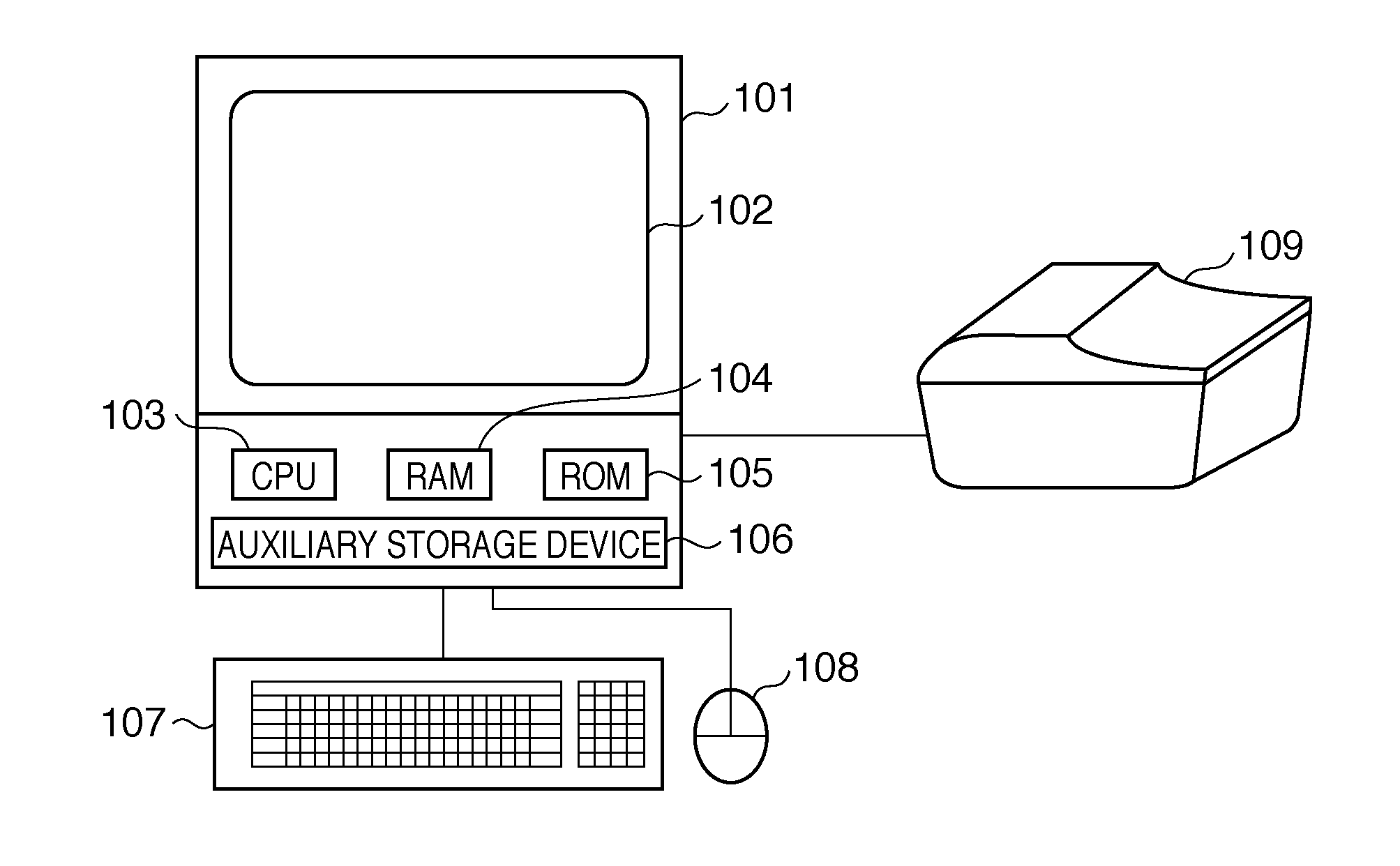
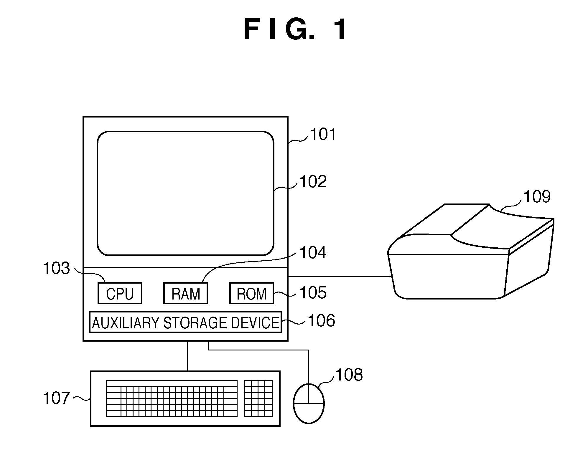
[0047]In the first embodiment, image reading using a 35-mm sleeve having six frames (frames A to F) will be described with reference to the flowcharts of FIGS. 3 to 7 and the display screen shown in FIGS. 8A to 9B.

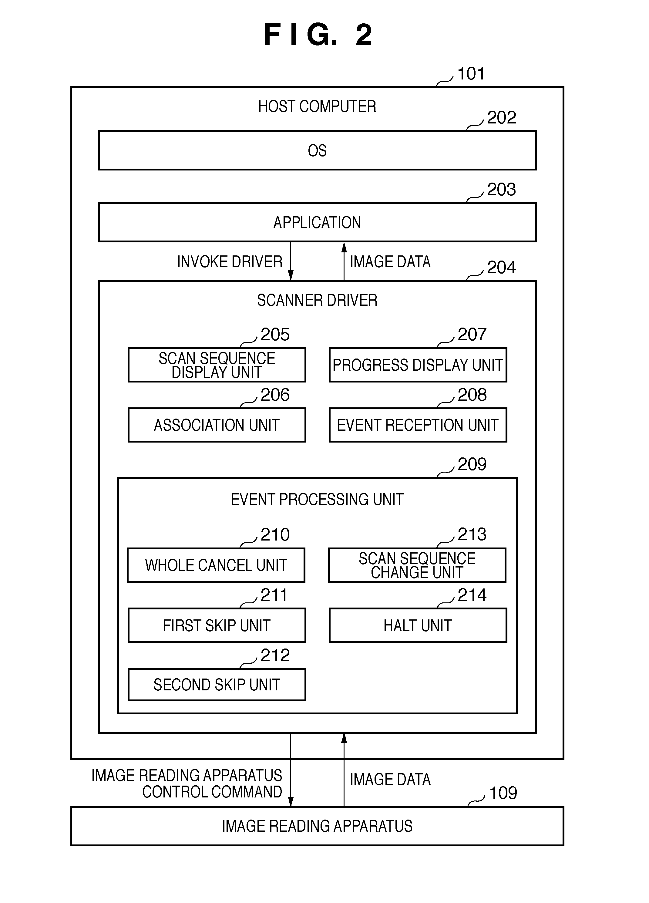
[0048]The user places one 35-mm sleeve on the original table of the image reading apparatus 109, activates the application 203 (S101), and activates the scanner driver 204 of the target image reading apparatus (S102). When the user executes preview (S103), the image reading apparatus performs pre-scan and displays a thus obtained preview image in the preview region (S104).

[0049]FIG. 8A shows a display screen serving as the UI (User-Interface) of the scanner driver 204. On the UI of the scanner driver 204, the user sets an original type 301, an output resolution 302, and an output size 303 and depresses a preview button 304 to execute preview. Image data obtained by the preview is displayed in a preview region 306. Note that in FIG. 8A, reference numeral 305 denotes a main ...

second embodiment

[0081]In the first embodiment, the progress is expressed using regions in crop frames. An example will be described here in which the progress of image reading is expressed using crop frames.

[0082]FIG. 10 is a view showing the progress of image reading according to the second embodiment. Referring to FIG. 10, a bold dotted line 701 expresses a crop frame currently under scan, and a bold line 702 expresses a crop frame to be scanned next. In FIG. 10, a frame A is being scanned. the crop frame of the frame A is indicated by the bold dotted line 701, and that of a frame B to be scanned next is indicated by the bold line 702. In this state, the user cannot grasp the progress of the crop under scan. Hence, in the second embodiment, a progress bar 703 representing the progress of the crop under scan is displayed, as shown in FIG. 10. In this case, if the progress bar 703 overlaps a crop frame, the user cannot visually grasp the crop under scan or the crop to be scanned next. Hence, the di...


PUM


Abstract

The purpose of this invention is to facilitate visually grasping the progress of reading during reading of a plurality of images. To accomplish this, when placing a plurality of images on an original table and scanning and reading them, display is made to allow a user to grasp which image on a preview screen corresponds to the image under scan. In addition, after the start of main scan, the user can designate an image on the preview screen and cancel scan of the image and change the scan sequence.

Description

BACKGROUND OF THE INVENTION[0001]1. Field of the Invention[0002]The present invention relates to an image reading method, an image reading system, and an image reading apparatus. Particularly, the present invention relates to an image reading method, an image reading system, and an image reading apparatus, which allow a user to specifically grasp the progress of scan when scanning and reading a plurality of originals.[0003]2. Description of the Related Art[0004]Conventionally, many of scanner drivers installed in image reading apparatuses or host computers connected to them display a progress bar on the screen to indicate the progress of original reading. When reading a plurality of originals, the dialogue with the progress bar displays the ordinal number of the original that is being read. The dialogue with the progress bar includes a cancel button. When the user depresses the cancel button, the subsequent reading is wholly canceled.[0005]For example, Japanese Patent Laid-Open No. ...

Claims


Application Information

Patent Timeline
IPC IPC(8): H04N1/04
CPCH04N1/00241H04N1/0044H04N1/00442H04N2201/0416H04N2201/0081H04N2201/0094H04N2201/0098H04N1/3872
Inventor ISHIDA, TOMOYA
Owner CANON KK
Learn More