Method and apparatus for providing a relative location indication during a surgical procedure

a relative location and surgical technique, applied in the field of orthopedic guidewires, can solve the problems of difficult to maintain a steady frame of reference with respect to the patient, patient tissue may be slippery or unstable,

Active Publication Date: 2012-01-12
THE CLEVELAND CLINIC FOUND
View PDF5 Cites 173 Cited by
  • Summary
  • Abstract
  • Description
  • Claims
  • Application Information

AI Technical Summary

Problems solved by technology

During a surgical procedure, it can be difficult to maintain a steady frame of reference with respect to the patient tissue within the surgical site.
In addition, the patient tissue may be slippery or unstable within the surgical site.

Method used


Image

  • Method and apparatus for providing a relative location indication during a surgical procedure
  • Method and apparatus for providing a relative location indication during a surgical procedure

Examples


Embodiment Construction

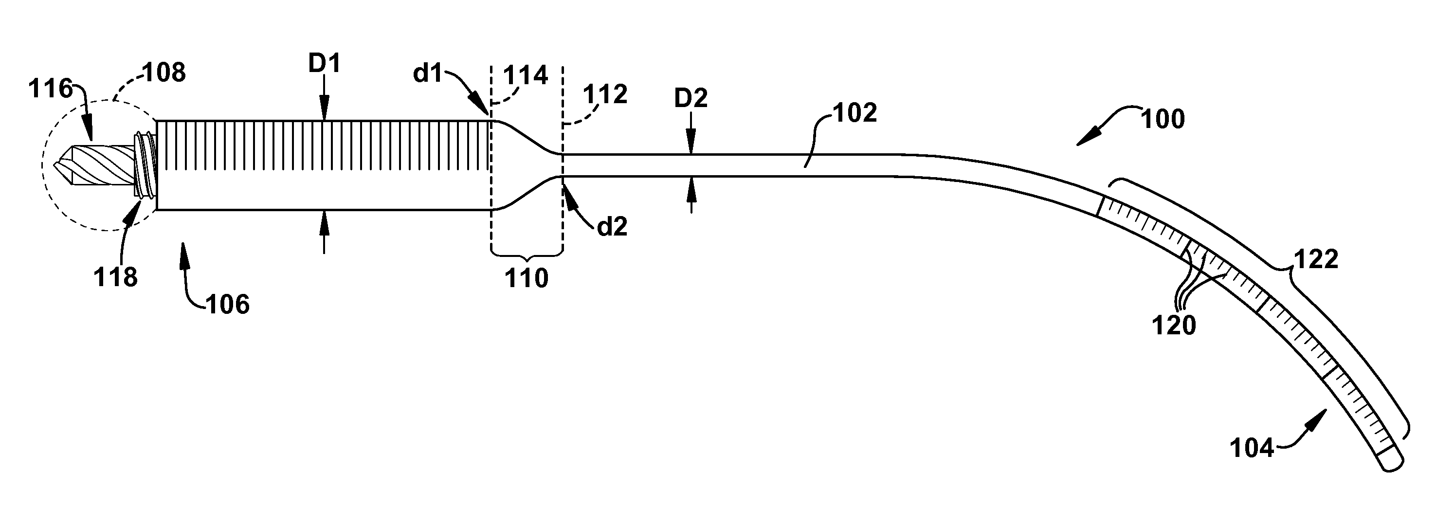
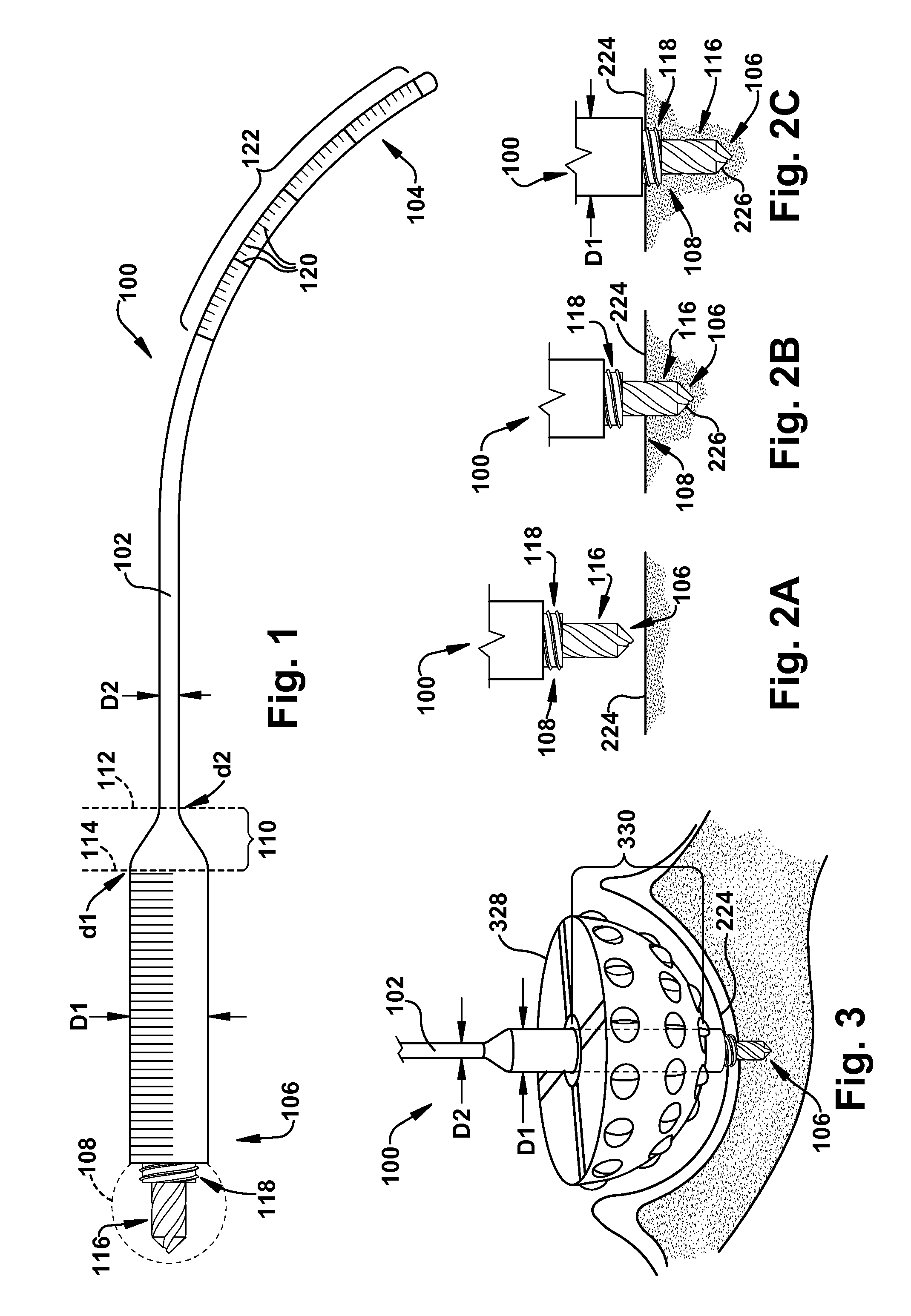
[0013]In accordance with the present invention, FIG. 1 depicts an orthopedic guidewire 100 for providing a relative location indication during a surgical procedure. An elongate guidewire body 102 has longitudinally spaced proximal and distal guidewire ends 104 and 106, respectively. The term “longitudinal” is used herein to refer to a direction defined by the length of the guidewire body 102, which is substantially horizontal in the orientation of FIG. 1. The term “lateral” is used herein to refer to a direction which is substantially perpendicular to the longitudinal direction; the lateral direction in FIG. 1 is into and out of the plane of the page.

[0014]An engaging feature 108 is located at the distal guidewire end 106 and is configured to selectively engage a patient tissue (not shown in FIG. 1). For clarity in the below description, the surface of the patient tissue will be described as a bone surface, such as that of an acetabulum or a glenoid vault, but may be any suitable pa...


PUM


Abstract

An orthopedic guidewire includes an elongate guidewire body having longitudinally spaced proximal and distal guidewire ends. An engaging feature is located at the distal guidewire end and is configured to selectively engage a bone surface. At least one of a variable diameter and a variable stiffness are along a portion of the guidewire body spaced apart from the engaging feature. A method of providing a relative location indication during a surgical procedure utilizing the orthopedic guidewire is also included.

Description

RELATED APPLICATION[0001]This application claims priority from U.S. Provisional Application No. 61 / 362,722, filed 9 Jul. 2010, the subject matter of which is incorporated herein by reference.TECHNICAL FIELD[0002]The present invention relates to an apparatus and method for providing a relative location indication during a surgical procedure and, more particularly, to an orthopedic guidewire and method for use.BACKGROUND OF THE INVENTION[0003]During a surgical procedure, it can be difficult to maintain a steady frame of reference with respect to the patient tissue within the surgical site. For example, the surgery may modify the patient tissue, the patient tissue may move within the patient's body, blood may obscure the patient tissue, local anatomic conditions may require that the patient tissue may be viewed or manipulated at an awkward angle for the surgeon, or the like. In addition, the patient tissue may be slippery or unstable within the surgical site.[0004]Accordingly, a guide ...

Claims


Application Information

Patent Timeline
Patent Type & Authority Applications(United States)
IPC IPC(8): A61B17/00
CPCA61B17/1746A61B17/8897A61B19/46A61B2019/462A61B2019/307A61B17/16A61B2019/306A61B90/06A61B2090/036A61B2090/037A61B2090/062
Inventor BARSOUM, WAEL K.
Owner THE CLEVELAND CLINIC FOUND
Why Eureka
Try Eureka