Systems and methods for mounting landing gear strain sensors

a technology of strain sensor and mounting system, which is applied in the direction of force measurement, instruments, transportation and packaging, etc., can solve the problems of affecting the detected resistance, unnecessary inspection or inspection, and cataclysmic failure, and achieves good accuracy and resolution, and large strains

Active Publication Date: 2012-01-19
THE BF GOODRICH CO
View PDF7 Cites 25 Cited by
  • Summary
  • Abstract
  • Description
  • Claims
  • Application Information

AI Technical Summary

Benefits of technology

[0006]The present invention provides a monitor for measuring loads on aircraft landing gear. This is done by measuring strains in the lower end of the strut, from which we infer the loading in the entire landing gear structure. These strains can be very large (as high as 10,000 microstrain) and can be imposed in numerous random directions and levels. The present invention includes a removable sensor assembly. An electromechanical means is presented that can accommodate large strains, be firmly attached to the strut, and provide good accuracy and resolution.

Problems solved by technology

Aircraft landing gear, among other support devices, can experience strains that might lead to catastrophic failure.
Subjective determination of when landing gear should be inspected or replaced may be over- or under-reported, leading to unnecessary inspections or a missed opportunity to inspect.
However, in real applications, temperature, material properties, the adhesive that bonds the gauge to the surface, and the stability of the metal all affect the detected resistance.
Furthermore, the sensing range of usual strain gauges is limited by maximum stress capability of the sensing element.
For example, the maximum strain limitation of these types of strain gauges is 3,000 microstrain. FIG. 1 shows fatigue limits on foil gauges.

Method used


Image

  • Systems and methods for mounting landing gear strain sensors
  • Systems and methods for mounting landing gear strain sensors
  • Systems and methods for mounting landing gear strain sensors

Examples


Embodiment Construction

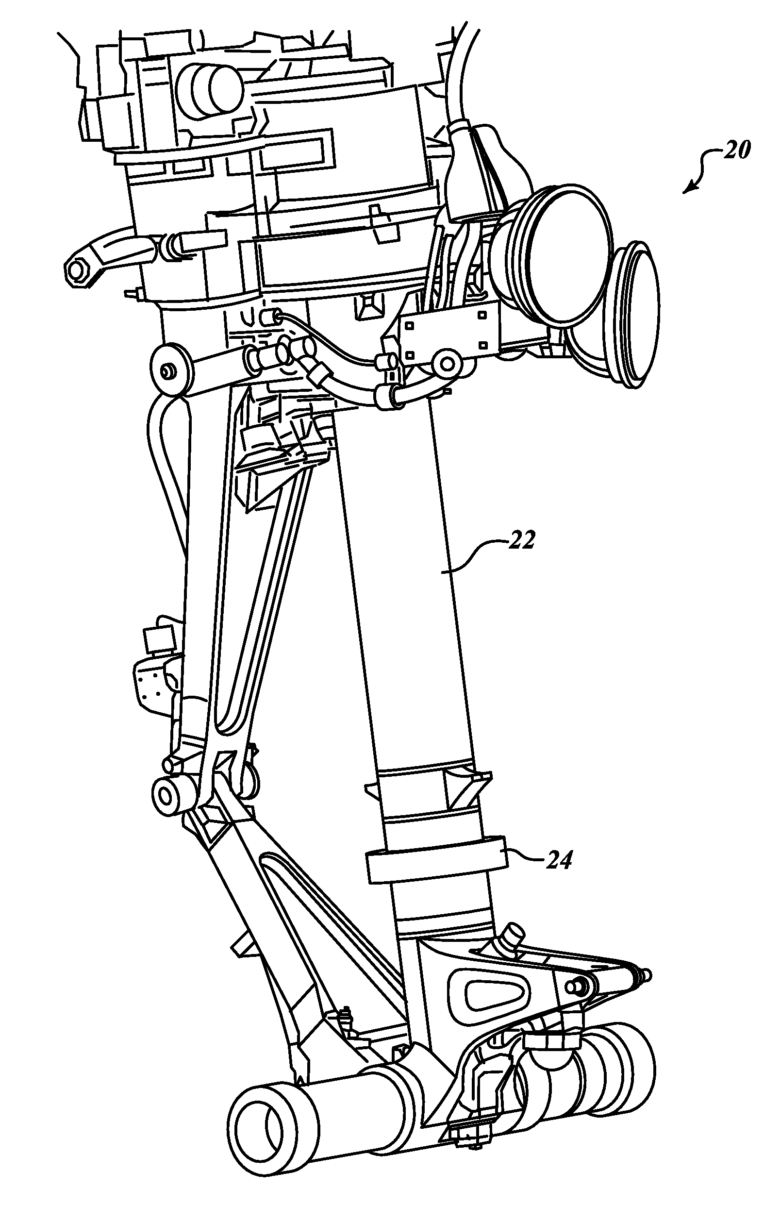
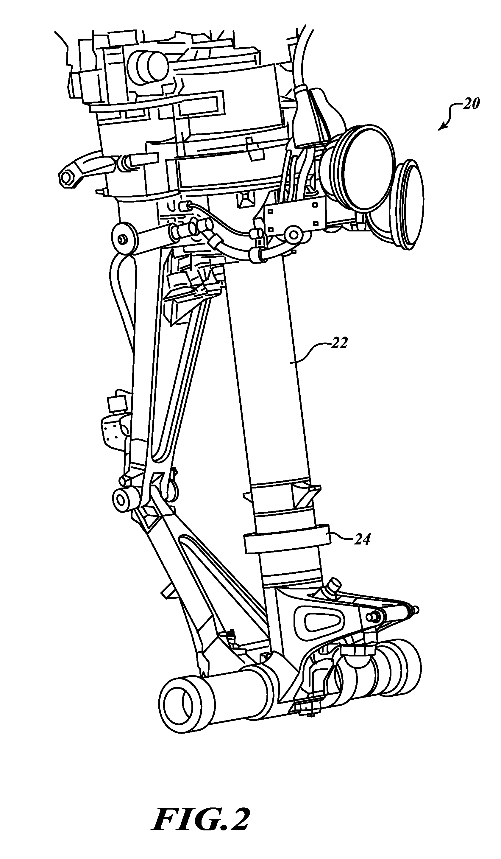
[0021]FIG. 2 is a perspective view of a landing gear assembly 20 that includes a strut piston 22. A sensor ring assembly 24 is mounted to the strut piston 22. The sensor ring assembly 24 includes one or more sensors that provide signals of stress or strain experienced by the strut piston 22. Exemplary sensors are described in copending U.S. patent application Ser. Nos. ______ and ______ filed ______ [attorney docket nos. (209AS148) GORI-1-1019 and (209AS057) GORI-1-1020].

[0022]As shown in FIGS. 3-5, an exemplary sensor ring assembly 24-1 includes two independently mounted rings 30, 32 that are secured to respective guide / anchor rings / splines 42. Each of the two rings 30, 32 includes a pair of joined C sections (halves). The joined C sections form a complete ring encircling the landing gear strut piston 22. The anchor rings / splines 42 may be an integral feature (spline) machined into the structure (the strut piston 22) or attached as separate bonded rings where close diametral tolera...


PUM


Abstract

A strain sensor device for measuring loads on aircraft landing gear. This is done by measuring strains in the lower end of the strut, by which we infer the loading in the entire landing gear structure. These strains can be very large (as high as 10,000 microstrain) and can be imposed in numerous random directions and levels. The present invention includes a removable sensor assembly. An electromechanical means is presented that can accommodate large strains, be firmly attached to the strut, and provide good accuracy and resolution.

Description

COPENDING APPLICATIONS[0001]U.S. patent application Ser. Nos. ______ and ______ filed ______, [attorney docket nos. (209AS148) GORI-1-1019 and (209AS057) GORI-1-1020], which are hereby incorporated by reference.BACKGROUND OF THE INVENTION[0002]Aircraft landing gear, among other support devices, can experience strains that might lead to catastrophic failure. During landing, a landing gear strut can be deformed due to strain in different directions. Subjective determination of when landing gear should be inspected or replaced may be over- or under-reported, leading to unnecessary inspections or a missed opportunity to inspect.[0003]Strain is defined as the amount of deformation per unit length of an object when a load is applied. Strain is calculated by dividing the total deformation of the original length by the original length (L):Strain(e)=(ΔL) / L [0004]For a polysilicon piezoresistive type-element, the resistance is changed with load applied. When a strain is introduced, the strain...

Claims


Application Information

Patent Timeline
Patent Type & Authority Applications(United States)
IPC IPC(8): G01D21/00
CPCB64C25/001G01L1/142B64D2045/008B64C25/60G01B7/22
Inventor ERIKSEN, ODD HARALD STEENGUO, SHUWENLIN, CHUANG-CHIASTANG, LAWRENCE JOSEPH
Owner THE BF GOODRICH CO
Why Eureka
Try Eureka