
Device for separating flat articles, a corresponding control method, and a corresponding postal machine

a flat article and control method technology, applied in the direction of article separation, conveyor parts, thin material processing, etc., can solve the problems of unsatisfactory effectiveness, unsatisfactory solutions, and inability to produce mailpieces, so as to ensure the integrity of the articles

Inactive Publication Date: 2012-01-19
SOLYSTIC
View PDF3 Cites 24 Cited by
  • Summary
  • Abstract
  • Description
  • Claims
  • Application Information

AI Technical Summary

Benefits of technology

[0014]An object of the invention is to remedy those drawbacks. A particular object of the invention is to propose a device making it possible to separate substantially all of the multiple takes that it might have to handle. An object of the invention is also to propose such a device that makes it possible to guarantee the integrity of the articles that are conveyed in it.
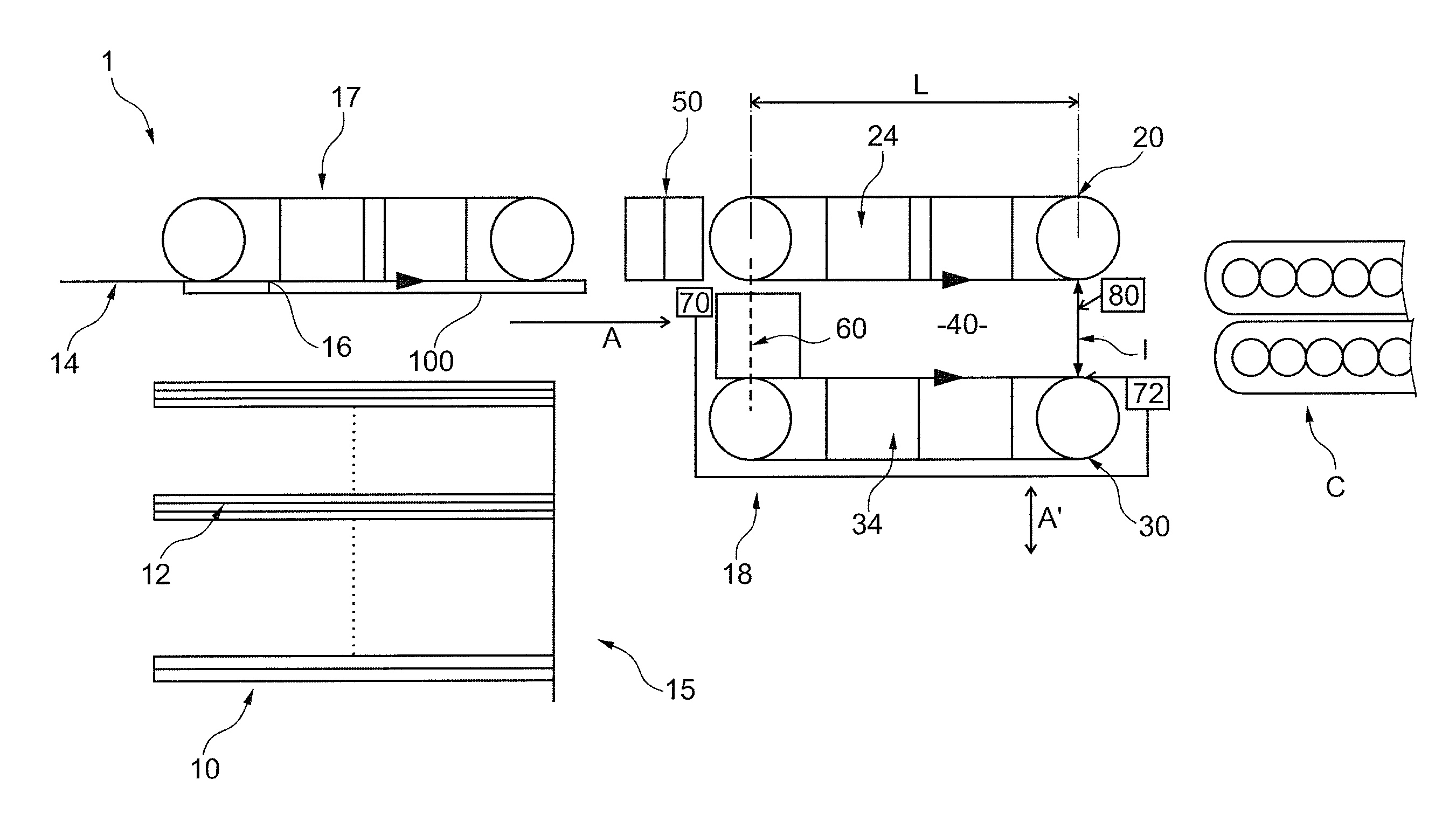
[0016]The basic idea of the invention is to generate an essentially transverse force on the mailpieces in order to separate them, rather than exerting a longitudinal force as in the prior art. This is less aggressive for the mailpieces, and makes it possible to reduce the total length of the device.

Problems solved by technology

However, it can happen that two adjacent mailpieces overlap, so that they then form a “multiple take”.
In which case, the mailpieces cannot be processed productively.
Unfortunately, that solution suffers from certain drawbacks.
Its effectiveness is rather unsatisfactory because, in practice, it has been observed that that solution does not guarantee systematic separation of the mailpieces bunched together in a multiple take.
In addition, it is relatively aggressive insofar as it might damage fragile mailpieces such as open ones or plastic-wrapped ones.
Unfortunately, such devices do not make it possible to obtain accurate and reproducible unstacking while also preserving the integrity of the articles.

Method used


Image

  • Device for separating flat articles, a corresponding control method, and a corresponding postal machine
  • Device for separating flat articles, a corresponding control method, and a corresponding postal machine
  • Device for separating flat articles, a corresponding control method, and a corresponding postal machine

Examples


Embodiment Construction

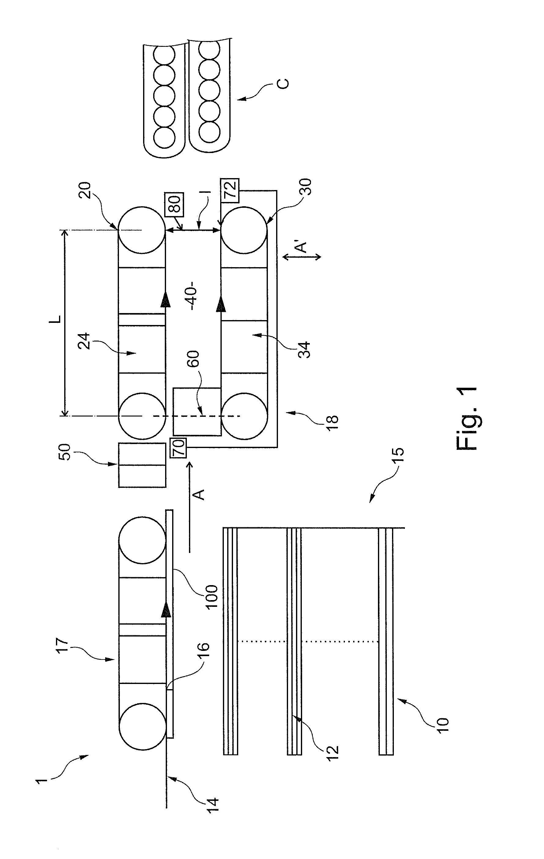
[0039]Firstly, FIG. 1 is a plan view of a device 1 making it possible to unstack flat articles that are, in this example, mailpieces. Firstly, this device includes a magazine 10 in which the mailpieces to be unstacked are disposed in a stack 12. This magazine is edged by an unstacker plate 14 against which the mailpieces bear, and by a jogging edge 15 that is substantially perpendicular to the unstacker plate.

[0040]A movement member 16 is also provided that is implemented in the form of a perforated belt co-operating with an unstacker solenoid valve 17. This member 16 is suitable for moving the first mailpiece 100 in the stack that is resting against the plate 14 in an unstacking direction indicated by the arrow A. This direction is parallel to the unstacker plate 14, namely horizontal in the figures, while also extending rightwards. The various above mechanical members are of conventional type, so that they are not described in any further detail below.

[0041]Downstream from the mov...


PUM

PropertyMeasurementUnit
Distanceaaaaaaaaaa
Distanceaaaaaaaaaa
Distanceaaaaaaaaaa

Abstract

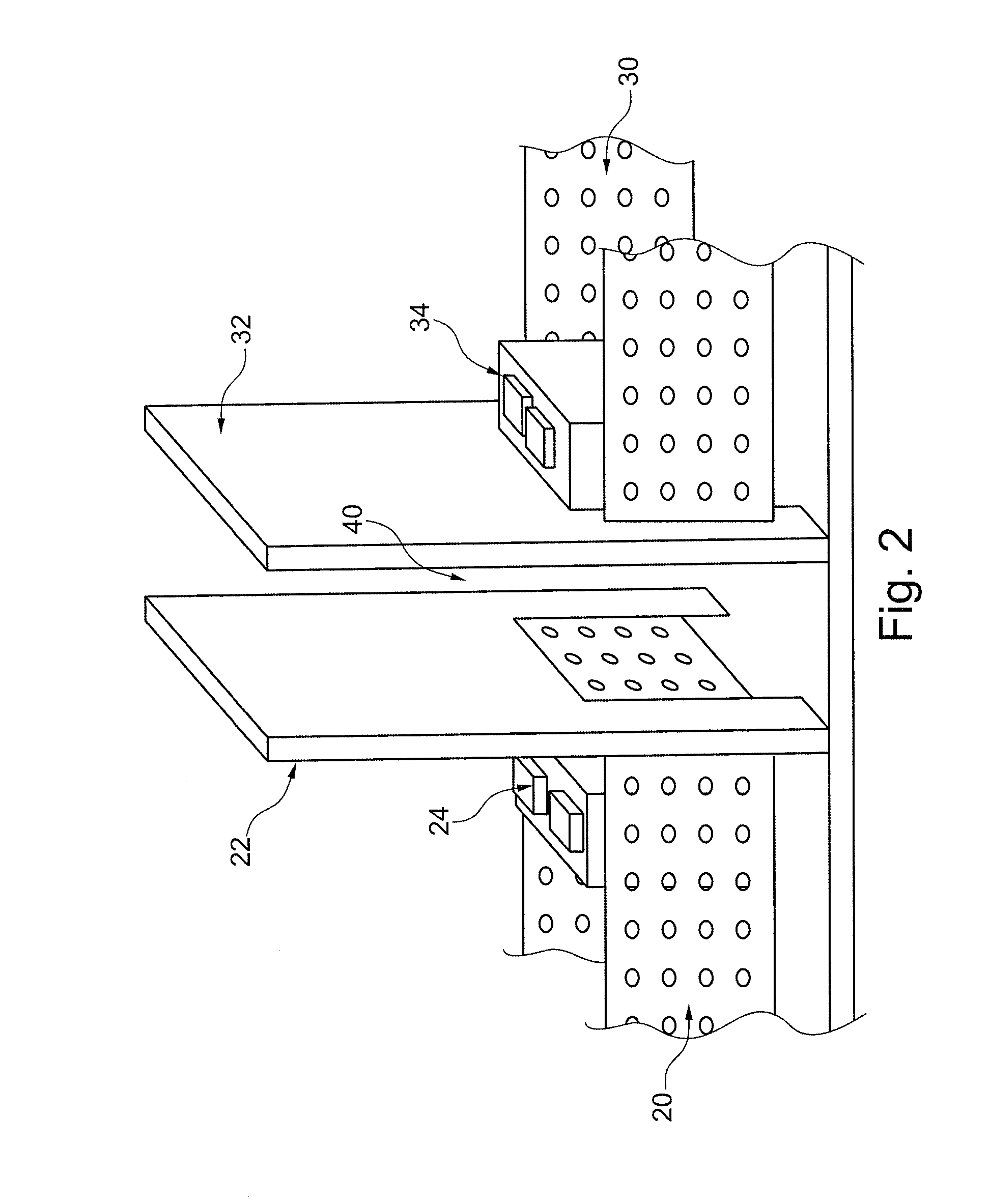
The invention relates to a separator device (18) comprising a passage zone (40) through which the articles pass and which extends between drive means (20, 30), retaining means (24, 34) for retaining an article relative to another article, and suitable for separating them mutually, control means suitable for activating and deactivating, independently, each first and second drive means (20, 30), and each first and second retaining means (24, 34). The drive means (20, 30) are distant from each other so as to define the passage zone (40), and the retaining means (24, 34) are suitable for exerting substantially transverse forces in opposite directions, so as to suck at least one article against corresponding drive means. The invention also relates to a method of controlling the above-mentioned separator device (18), and to a postal sorting machine including such a separator device (18).

Description

CROSS REFERENCE TO RELATED APPLICATION(S)[0001]This application is a 35 U.S.C. §371 National Phase Entry Application from PCT / FR2011 / 050519, filed Mar. 15, 2011, designating the United States and also claims the benefit of French Application No. 1052335, filed Mar. 30, 2010, the disclosures of which are incorporated herein by reference in their entirety.TECHNICAL FIELD[0002]The invention relates to the field of unstacking flat articles from a stack of flat articles, in particular small-format mailpieces, such as letters, or indeed large-format mailpieces, such as magazines, so as to put them into series and so as to transport them in series in a conveyor. The invention relates more particularly to separating such mailpieces, when they are mutually overlapping and stuck together or bunched together, forming what, in the art, may be termed “multiple takes” or “multiple feeds” of mailpieces.PRIOR ART[0003]Usually, mailpieces are disposed on edge and in a stack in a magazine, facing an ...

Claims


Application Information

Patent Timeline
IPC IPC(8): B65H5/00B65G47/26B65H3/00
CPCB65H3/124B65H2701/1916B65H7/12B65H2301/22B65H2301/321B65H2406/32B65H2511/13B65H2511/22B65H2511/514B65H2511/524B65H2513/512B65H2513/514B65H2515/30B65H2515/342B65H2701/1311B65H2701/1313B65H3/46B65H2220/01B65H2220/02B65H2220/03B65H2515/34
Inventor AMBROISE, STEPHANESAMAIN, STEPHANEDAUVERGNE, MICKAEL
Owner SOLYSTIC
Learn More