[0019]According to the first aspect, the vehicle speed limiting system includes: the three-dimensional map that is provided to each of the gear stages of the transmission and from which to derive the target throttle
valve opening degree of the throttle valve on the basis of the throttle grip opening degree and the engine speed; and the throttle valve driving unit that drives the motor in accordance with the target throttle valve opening degree. In addition, when the speed of a vehicle is about to exceed the preset maximum speed, the throttle valve driving unit drives the motor in such a manner that the speed of the vehicle does not exceed the preset maximum speed, irrespective of the target throttle valve opening degree derived from the three-dimensional map. Accordingly, an influence to be given to the driving feeling of the vehicle is suppressed as compared to the systems that reduce the engine output by reducing the number of times of
fuel injection or by ignition
cut. As a result, a smooth maximum speed limiting control can be executed without giving any discomfort to the rider. Furthermore, the target throttle valve opening degree map for each gear stage of the transmission enables an optimum setting of the throttle valve opening degree with no consideration of the limit of vehicle speed, and thus allows the vehicle speed to be limited with various speeds without changing the setting of the map in conformity with any of maximum speed limitations that are different from one country to another.
[0020]According to the second aspect, the vehicle speed limiting system further includes the speed difference calculating means for calculating a difference between a current speed of the vehicle and the preset maximum speed; the acceleration calculating means for calculating an acceleration of the vehicle; and the maximum speed limiter opening degree calculating means for calculating the first maximum speed limiter opening degree by adding the first predetermined opening degree calculated by multiplying the speed difference by the preset P-term coefficient, the second predetermined opening degree calculated by multiplying the acceleration by the preset D-term coefficient, and the current throttle valve opening degree. In addition, the throttle valve driving unit is configured to drive the motor on the basis of the first maximum speed limiter opening degree once the calculated first maximum speed limiter opening degree falls below the target throttle valve opening degree derived on the basis of the three-dimensional map. Accordingly, the setting of the throttle valve opening degree in accordance with the difference between the current speed and the maximum speed as well as with the acceleration of the vehicle makes it possible to smooth the speed change of the vehicle from a state where the speed has approached the maximum speed to a state where the speed reaches the maximum speed. This eliminates, for example, such a case where the engine output is largely decreased to cause a large deceleration at the time when the speed of the vehicle reaches the maximum speed. As a result, a smooth maximum speed limiting control can be executed.
[0021]According to the third aspect, the vehicle speed limiting system further includes the low-select means for switching the first maximum speed limiter opening degree to the second maximum speed limiter opening degree, which is smaller than the first maximum speed limiter opening degree, in accordance with the change rate of the throttle grip opening degree when the throttle grip opening degree becomes small during the execution of the maximum speed limiting using the first maximum speed limiter opening degree. Accordingly, for example, even when the throttle grip is rapidly returned during the execution of the maximum speed limiting control, it is possible to switch the first maximum speed limiter opening degree to the second maximum speed limiter opening degree in response to the rotation operation of the throttle grip. This makes it possible to prevent an occurrence of the phenomenon where the throttle valve is not driven in the closing direction until the target throttle valve opening degree falls below the first maximum speed limiter opening degree even when the rider rotates the throttle grip in the closing direction. As a result, a smooth deceleration with no free running feeling can be achieved by giving no discomfort to the rider.
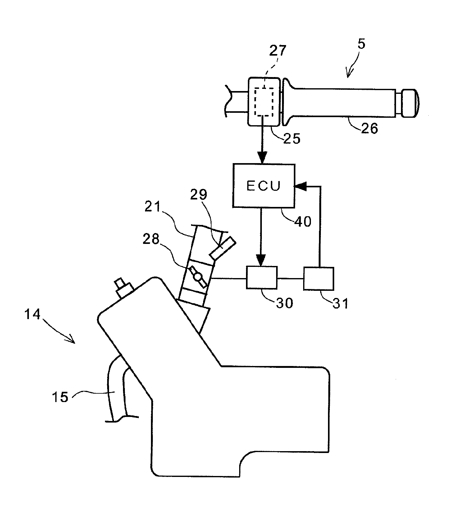
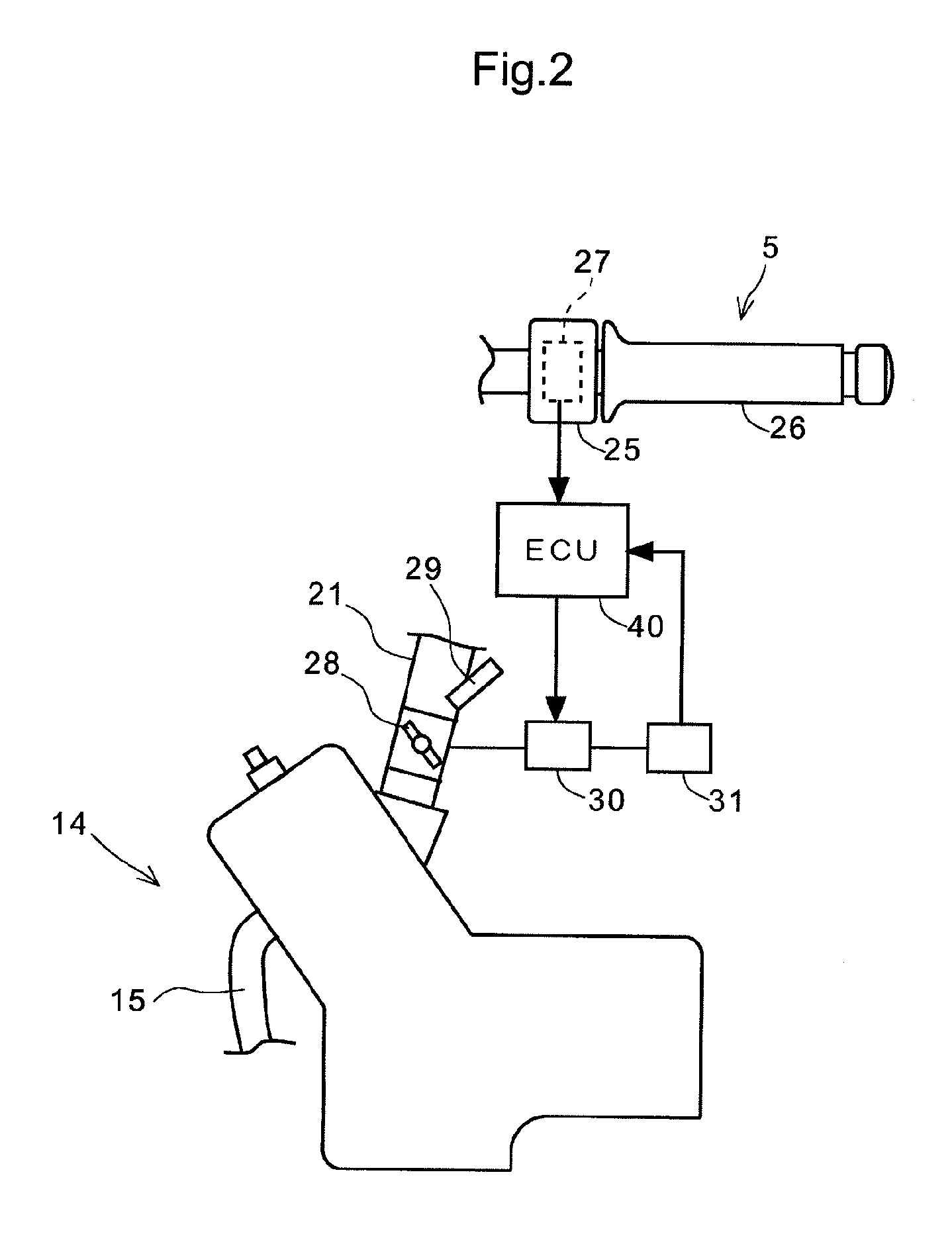
[0022]According to the fourth aspect, the vehicle speed limiting system is applied to an engine having a plurality of cylinders, the engine is configured to change a number of cylinders being operated by stopping at least one of the plurality of cylinders in accordance with a state of an operation of the vehicle, a plurality of motors that drives the throttle valve and that is equal in number to a number of stages of change of the number of cylinders being operated is provided, and the vehicle speed limiting system sets a target throttle valve opening degree in accordance with the number of cylinders being operated when the current vehicle speed reaches a preset set maximum vehicle speed, and uses the target throttle valve opening degree to control the plurality of motors. Therefore, for example, in an engine having a cylinder stop mechanism that can change the number of cylinders being operated from four to three and to two, the target throttle valve opening degree in accordance with the number of cylinders being operated is set, and thus it is possible to limit the maximum speed of a vehicle.
[0023]According to the fifth aspect, a maximum
speed limit target torque in which the current vehicle speed reaches the set maximum vehicle speed is operated, then the maximum
speed limit target torque is converted into a target throttle grip opening degree and then the target throttle valve opening degree is calculated as a value allocated to the number of cylinders being operated determined by the target throttle grip opening degree. Therefore, when the number of cylinders being operated is changed, the target throttle valve opening degree for achieving the same predetermined vehicle speed is changed, even in this case, since the maximum
speed limit target torque is temporarily converted into the target throttle grip opening degree, it is possible to set the throttle valve opening degree in accordance with the number of cylinders being operated and thereby limit the maximum speed.
[0024]According to the sixth aspect, the vehicle speed limiting system calculates a feedback operation amount based on a vehicle speed difference between the set maximum vehicle speed and the current vehicle speed, and an amount of variation in the vehicle speed difference, and calculates the maximum speed limit target torque by adding a target torque current value converted into the target throttle grip opening degree in a previous process to the feedback operation amount. Therefore, it becomes easier to execute a calculation process for the feedback operation amount for preventing the vehicle speed from exceeding the set maximum vehicle speed and a calculation process for the maximum speed limit target torque.

