Device and method for providing a user interface
a technology of user interface and device, applied in the field of device and method for providing user interface, can solve the problems of conventional touch-based user interface and inability to allow a variety of user touch inputs
- Summary
- Abstract
- Description
- Claims
- Application Information
AI Technical Summary
Benefits of technology
Problems solved by technology
Method used
Image
Examples
embodiment 1
[0096]Therefore, various instructions can be executed based on the generated information according to the type of instruction corresponding to a touched icon. Hereinafter, examples of instruction execution are provided.
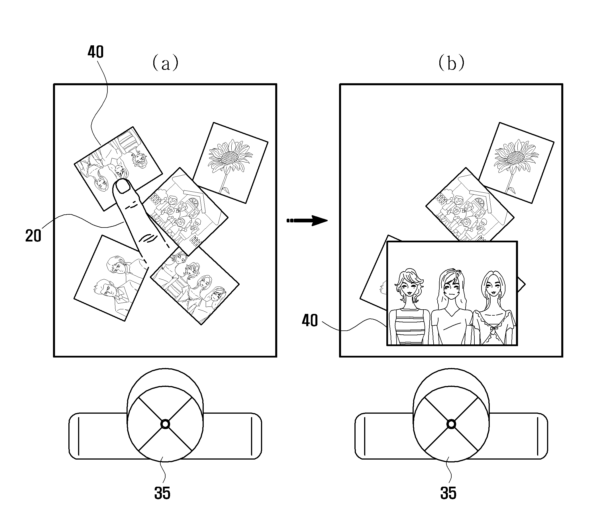
[0097]FIG. 5 illustrates a first example of instruction execution in the device of FIG. 1. In FIG. 5, a picture corresponding to a touched icon is displayed by rotating, moving, and enlarging the picture. The picture may then be situated at a location in the display unit 11 corresponding to the user's position.
[0098]As shown in FIG. 5(a), pictures may be displayed in a reduced thumbnail form and icons may be randomly arranged. When a user 35 touches an icon 40 in the display unit 11, the controller 13 may calculate the direction vector 33 of a finger image of the finger 20, measure a vector angle, and estimate a location of the user 35. In FIG. 5(a), the direction vector 33 of the finger 20 is in a range of 45° to 135°, hence a location of the user 35 may be determine...
embodiment 2
[0106]FIG. 9 is a perspective view illustrating a finger touch action in a user interface providing device using information based on a finger type according to exemplary embodiments of the present invention.
[0107]FIG. 9(a) illustrates an example in which a large portion of the lower part of the finger 20 touches the display unit 11 and a finger touch area 81 may be large. FIG. 9(b) illustrates an example in which only a tip portion of the finger 20 touches the display unit 11 and a finger touch area 82 may be small. Accordingly, different instructions can be executed according to a finger touch action.
[0108]FIG. 10 illustrates a first example of instruction execution in the device of FIG. 9. In FIG. 10, an upper-level menu or a lower-level menu may be displayed according to a finger touch form.
[0109]Referring to FIG. 10, if the finger touch area 81 is ‘large’, a lower-level menu corresponding to the touched icon may be displayed. Although not shown in FIG. 10, if the finger touch a...
embodiment 3
[0113]FIG. 12 is a perspective view illustrating a device using information based on a finger type according to exemplary embodiments of the present invention.
[0114]Referring to FIG. 12, the controller 13 may determine whether a touching finger is a right hand finger 111 or a left hand finger 112 using a direction vector 33 of the detected finger. Further, in some cases a direction vector 33 of the touching finger 20 cannot be determined because the touch action is performed at an end portion (e.g., at the right side or the left side) of the display unit 11 such that the finger non-touch area 32 is not determined. If the direction vector 33 cannot be determined, the controller 13 may determine whether the touching finger is the right hand finger 111 or the left hand finger 112 based on whether the finger touch area 31 is towards the right side or the left side of the display unit 11. The controller 13 may execute an instruction according to the determined finger type information.
[01...
PUM
 Abstract
Description
Claims
Application Information
 - R&D
- Intellectual Property
- Life Sciences
- Materials
- Tech Scout
- Unparalleled Data Quality
- Higher Quality Content
- 60% Fewer Hallucinations
Browse by: Latest US Patents, China's latest patents, Technical Efficacy Thesaurus, Application Domain, Technology Topic, Popular Technical Reports.
© 2025 PatSnap. All rights reserved.Legal|Privacy policy|Modern Slavery Act Transparency Statement|Sitemap|About US| Contact US: help@patsnap.com


