
Method and device for adaptive noise measurement of a video signal

a video signal and noise measurement technology, applied in the field of video signal adaptive noise measurement, can solve the problems of inability to use the method anymore as often and as easily, poor signal storage or transmission, and video signals that are often disturbed by noise, and achieves reliable results, low effort, and easy implementation.

Active Publication Date: 2012-01-26
SONY CORP
View PDF7 Cites 18 Cited by
  • Summary
  • Abstract
  • Description
  • Claims
  • Application Information

AI Technical Summary

Benefits of technology

[0007]It is an object of the present invention to provide a method and a corresponding device for adaptive noise measurement of a video signal comprising a sequence of images, which do not require the use of a noise-free reference image, are easily implementable with low efforts and provide reliable results with any kind of video signals. It is a further object of the present invention to provide a corresponding computer-readable non-transitory medium storing such a computer program.

Problems solved by technology

Video signals are often disturbed by noise.
This noise can come from analogue or digital photography, where it may originate from short exposure times or photo sensor properties.
It can also come from bad signal storage or transmission, for example if the signal was deteriorated and amplified many times.
Nowadays, video sequences may not have such a known black area anymore, so that this method can not be used anymore as often and as easily as in earlier times.

Method used


Image

  • Method and device for adaptive noise measurement of a video signal
  • Method and device for adaptive noise measurement of a video signal
  • Method and device for adaptive noise measurement of a video signal

Examples


Embodiment Construction

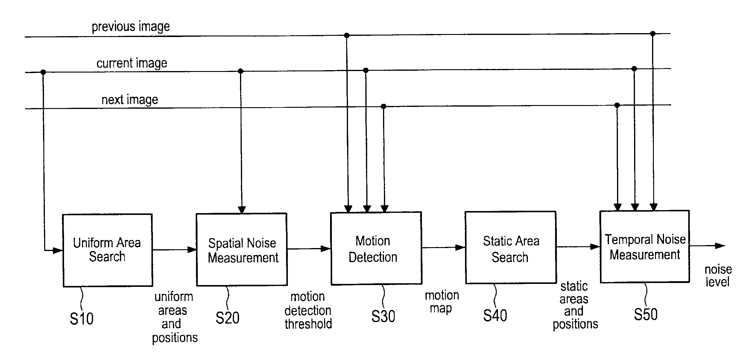
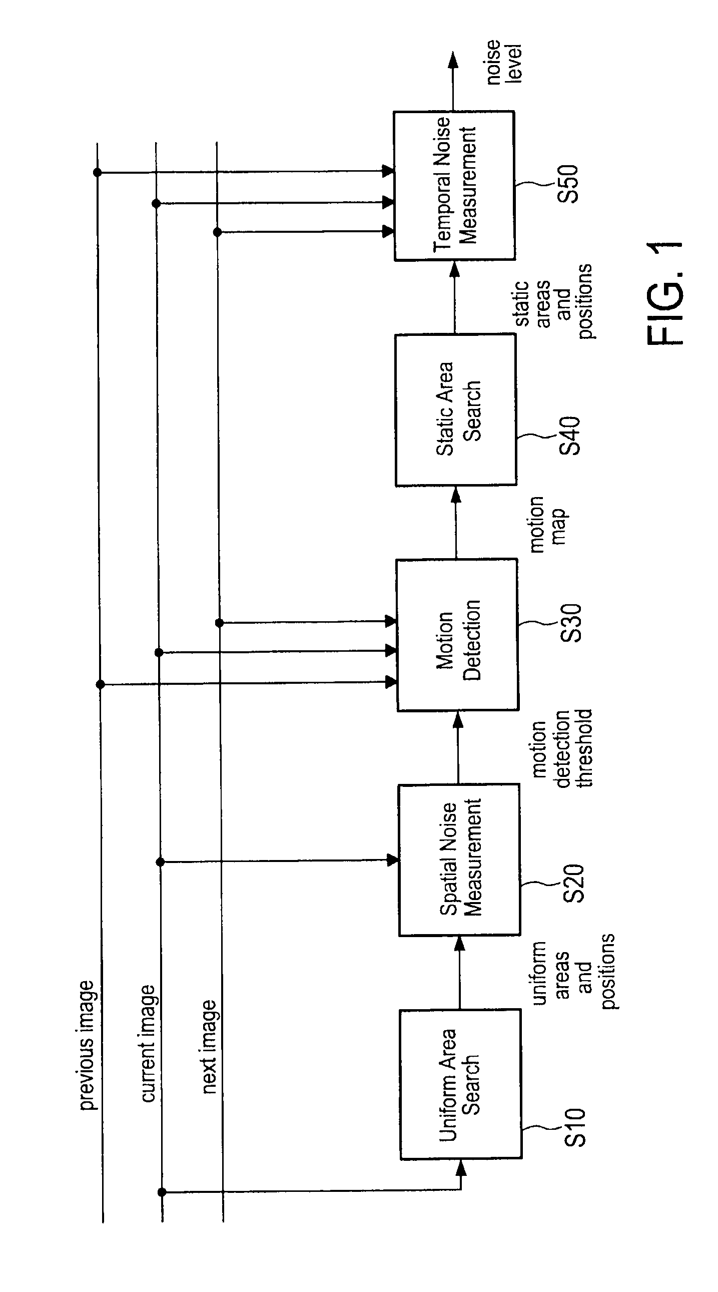
[0044]According to the present invention a method employing multi-stage processing is provided, which may be repeated for selected or each input image (or frame) of a video signal comprising a sequence of images. Exemplarily, the proposed method shall be explained with reference to the diagrams shown in FIGS. 1 to 6 illustrating the steps of the proposed method. In particular, FIG. 1 illustrates an overview over the essential steps of the proposed method, and FIGS. 2 to 6 illustrated said steps separately with more detail.

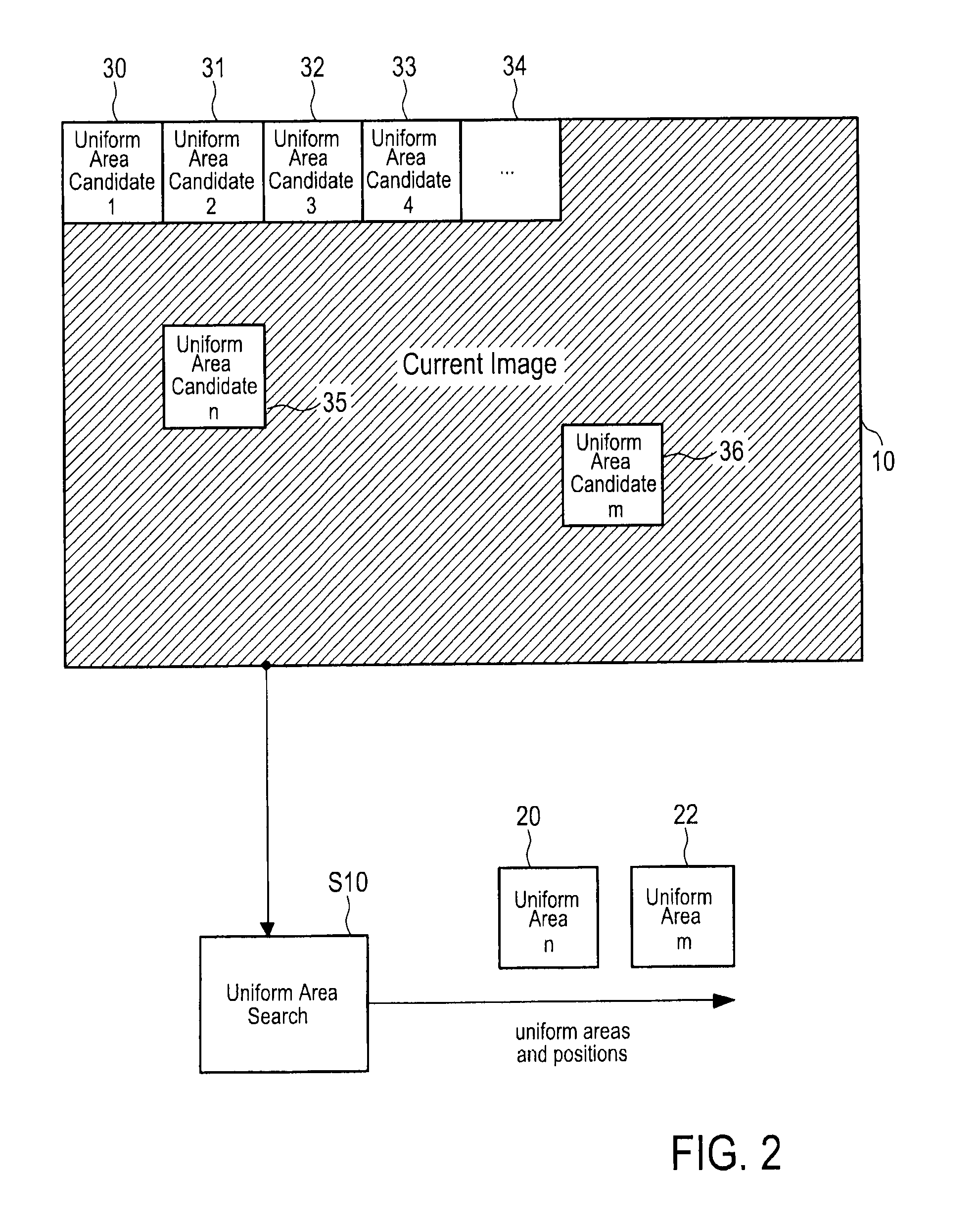
[0045]In a first step S10, illustrated in detail in FIG. 2, a uniform area search is performed, i.e. one or more spatially uniform areas 20, 22 within a current image 10 are searched.

[0046]One image, for instance the first image, of the video sequence is searched for (spatially) uniform areas, i.e. for the area with the least amount of detail. This is, for instance, done by repeatedly selecting different (candidate) areas (also called blocks) 30, 31, 32, 33, 34, 35...


PUM


Abstract

The present invention relates to method of adaptive noise measurement of a video signal comprising a sequence of images. The proposed method comprises the steps of searching one or more spatially uniform areas within a current image, determining a spatial uniformity value of said one or more spatially uniform areas and combining said spatial uniformity values to obtain a spatial noise value representing a first measure for the amount of noise in said current image, detecting motion by comparing the current image with one or more preceding images and / or one or more succeeding images of said sequence of images by use of a motion threshold to obtain one or more motion maps indicating the amount of motion between the current image and the respective preceding or succeeding image, searching one or more static areas within said one or more motion maps, determining a temporal uniformity value for said one or more static areas by comparing image values at positions in said one or more preceding images and / or said one or more succeeding images, at which a low amount or no motion is indicated in the respective one or more motion maps, said temporal uniformity value representing a measure for the amount of noise at said positions in said current image, and combining said obtained temporal uniformity values to obtain a combined noise value representing a second measure for the amount of noise in said current image.

Description

FIELD OF THE INVENTION[0001]The present invention relates to a method of adaptive noise measurement of a video signal comprising a sequence of images and to a corresponding device. Further, the present invention relates to a computer readable non-transitory medium.BACKGROUND OF THE INVENTION[0002]Video signals are often disturbed by noise. The most frequent type of noise is frame noise, also called analogue noise, which is furthermore just called noise in this invention. (Other noise types would be frame noise, block noise or mosquito noise, which are both not addressed here.) This noise can come from analogue or digital photography, where it may originate from short exposure times or photo sensor properties. It can also come from bad signal storage or transmission, for example if the signal was deteriorated and amplified many times.[0003]This noise is usually uniformly distributed over the whole image. It may be correlated to some properties of the image, like brightness or contras...

Claims


Application Information

Patent Timeline
Patent Type & Authority Applications(United States)
IPC IPC(8): H04N17/00
CPCH04N5/145H04N17/004H04N5/21
Inventor MOESLE, FRANKSPRINGER, PAULSCHEWIOR, GREGOR
Owner SONY CORP
Learn More