
Method and system arranged for filtering an image

a filtering system and image technology, applied in image enhancement, image analysis, instruments, etc., can solve the problems of adversely affecting video quality, and low frequency flickering of images where high spatial vertical frequency

Inactive Publication Date: 2012-01-26
NXP USA INC
View PDF3 Cites 17 Cited by
  • Summary
  • Abstract
  • Description
  • Claims
  • Application Information

AI Technical Summary

Benefits of technology

[0007]These and other aspects of the invention will be apparent from, and elucidated with reference to, the examples described hereinafter.

Problems solved by technology

However, limitations of camera sensors, video compression, transmission of the video through communication channels adversely affect the video quality due to unwanted effects.
The alternating of the display of odd and even lines can result in flickering of the image.
Flickering can be seen as an aliasing phenomenon, and is the effect caused when high frequency image energy aliases to low frequency image energy, thereby resulting in low frequency flicker where high spatial vertical frequencies are present.
Other unwanted effects can include noise, contrast degradation blur, ringing and the like.

Method used


Image

  • Method and system arranged for filtering an image
  • Method and system arranged for filtering an image
  • Method and system arranged for filtering an image

Examples


Embodiment Construction

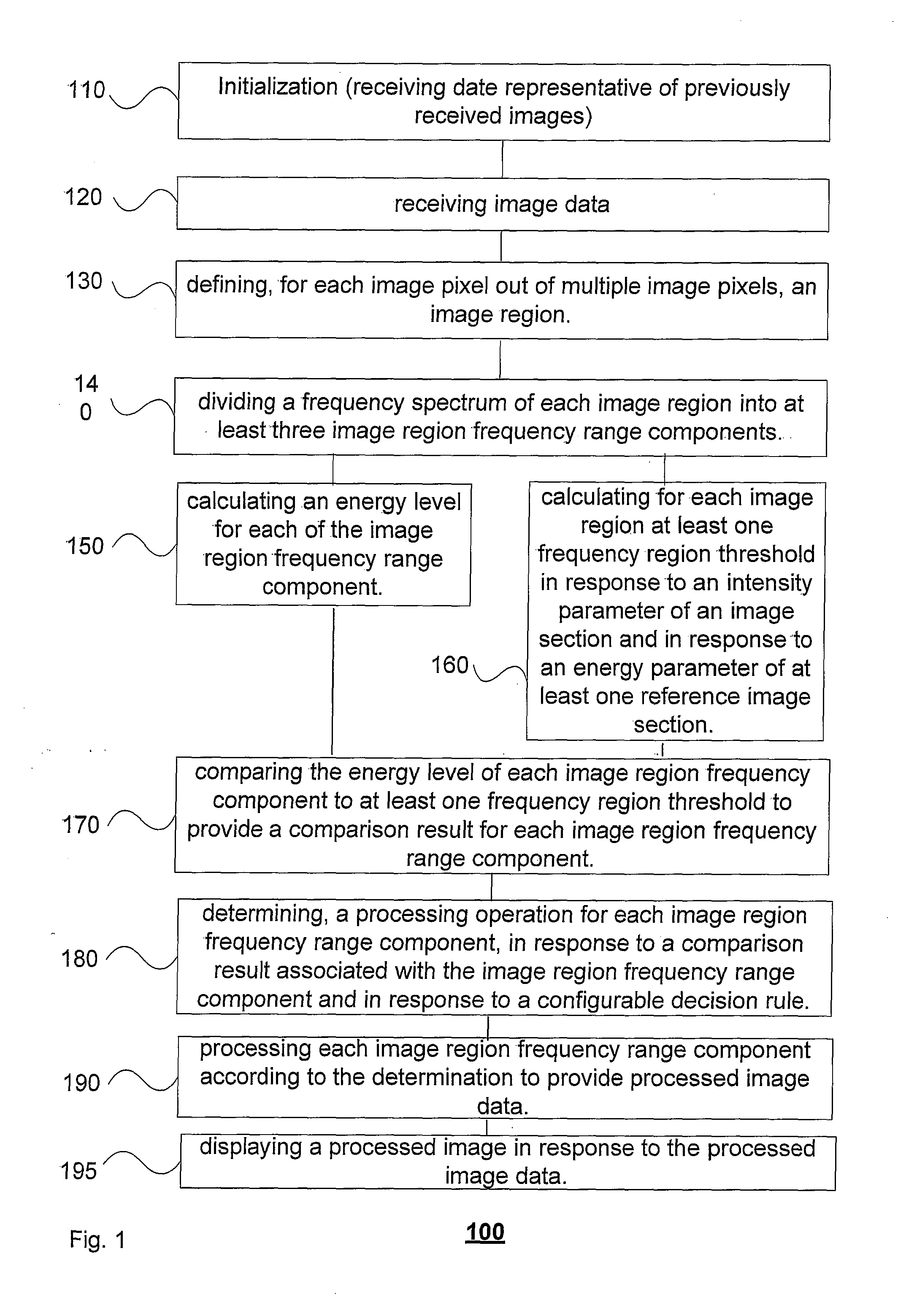
[0018]FIG. 1 illustrates an example of an embodiment of a method 100 for filtering image data to be displayed.

[0019]Method 100 starts by initialization stage 110. Initialization stage 110 can include receiving date representative of previously received images.

[0020]Stage 110 is followed by stage 120 of receiving image data. The image data represents an image. The image may include a plurality of pixels, e.g. arranged in multiple rows and columns. An image can include any suitable number of pixels, such as from a few thousand up to millions of pixels.

[0021]The image data can include one or more components such as a Red component of the image, a Green component of an image, a blue component of an image. Yet for another example the image data can include a Luma component of the image, two Chroma components of an image and the like.

[0022]Stage 120 is followed by stage 130 of defining, for each image pixel out of multiple image pixels, an image region. Accordingly, an image region can be...


PUM


Abstract

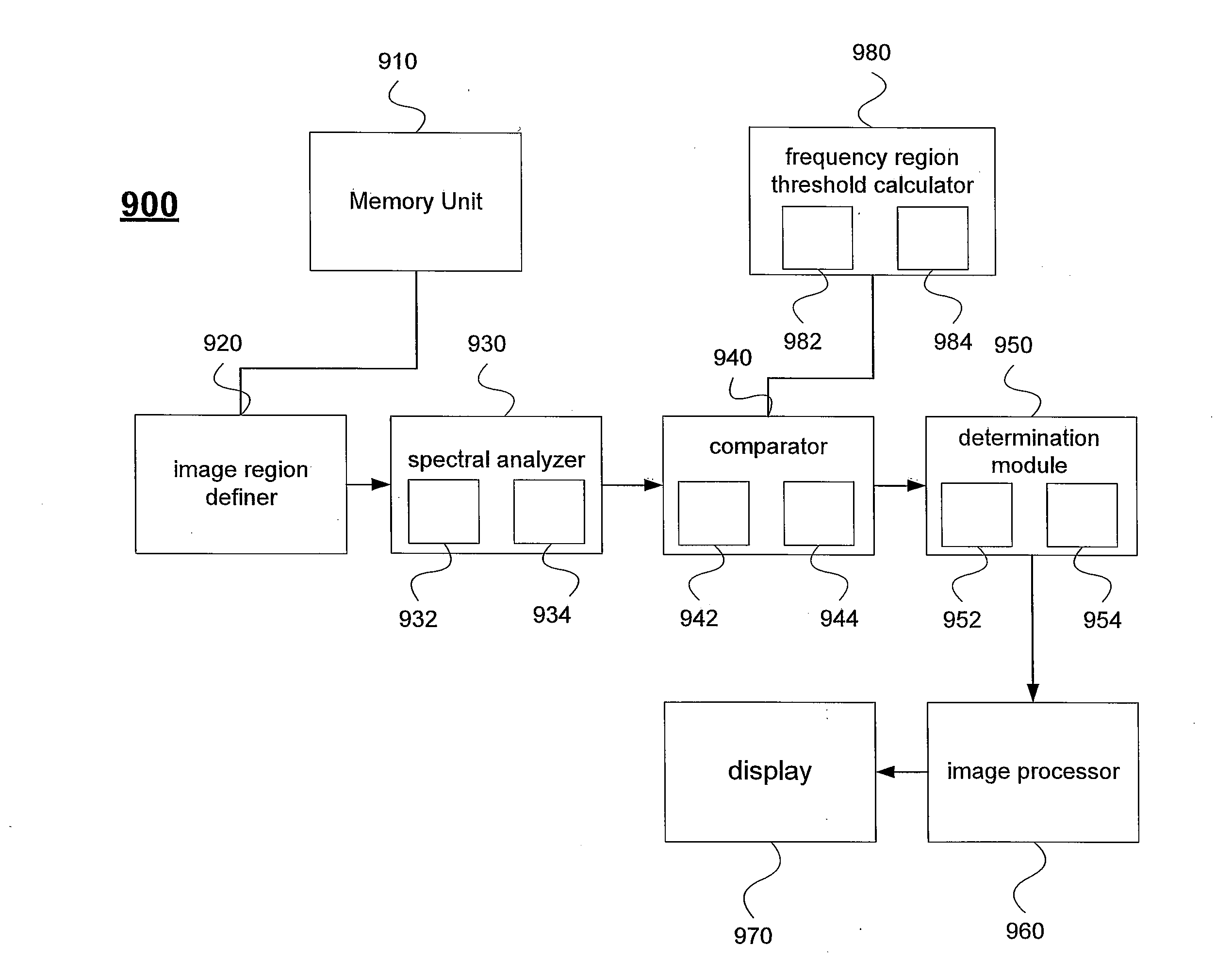
A method and a system, the system includes: a memory unit, an image region definer, a spectral analyzer, a determination module, and an image processor. The spectral analyzer is arranged to divide a frequency spectrum of each image region into at least three image region frequency range components (IRFRCs); and calculate an energy level for each IRFRC. The comparator configured to compare the energy level of each IRFRC to at least one frequency region threshold to provide a comparison result for each IRFRC; wherein each frequency region threshold is calculated based on an intensity parameter of an image section and based on an energy parameter of at least one reference image section; a determination module arranged to determine a processing operation for each IRFRC, based on a comparison result associated with the IRFRC and based on a configurable decision rule.

Description

FIELD OF THE INVENTION[0001]The field of this invention relates to a system and a method for filtering an image / video using multiple filters.BACKGROUND OF THE INVENTION[0002]Modern consumer multimedia devices (such as portable media players, personal navigation devices, mobile internet device etc) typically have the capability to provide (high quality) video output, e.g. at a display of the device. However, limitations of camera sensors, video compression, transmission of the video through communication channels adversely affect the video quality due to unwanted effects.[0003]Flickering is an example of such an unwanted effect. It can occur in television systems and the like that use an interlaced scan line technique in order to minimize the signal bandwidth used. With the interlaced scan line technique, an image is displayed as two scan line fields; one scan line field comprising the odd horizontal lines of the image; and the second scan line field comprising the even horizontal li...

Claims


Application Information

Patent Timeline
IPC IPC(8): G06K9/34
CPCG06T5/00G06T2207/20048G06T2207/30148G06T5/10G06T2207/20021H04N23/745
Inventor ZARUBINSKY, MICHAELBEER-GINGOLD, SHLOMOKOSASHVILI, MICHELLE
Owner NXP USA INC
Learn More