
Systems and Methods for Optimizing and Maintaining Visualization of a Surgical Field During the Use of Surgical Scopes

a surgical field and visualization technology, applied in the field of surgical scopes, can solve the problems of generating mist, smoke and other debris, inconvenient for the scope operator and the surgeon, and becoming suspended throughout the expanded abdominal spa

Inactive Publication Date: 2012-01-26
FLOSHIELD INC
View PDF5 Cites 22 Cited by
  • Summary
  • Abstract
  • Description
  • Claims
  • Application Information

AI Technical Summary

Problems solved by technology

The local environment within a patient's abdominal space is generally rather warm and humid, and the use of devices such as harmonic scalpels and other cutting and coagulating devices generate mist, smoke, and other debris that is released into the surgical field and often becomes suspended throughout the expanded abdominal space.
The need to remove the scope to defog and remove debris from the lens is inconvenient for the scope operator and the surgeon and can interrupt and undesirably prolong surgical procedures.

Method used


Image

  • Systems and Methods for Optimizing and Maintaining Visualization of a Surgical Field During the Use of Surgical Scopes
  • Systems and Methods for Optimizing and Maintaining Visualization of a Surgical Field During the Use of Surgical Scopes
  • Systems and Methods for Optimizing and Maintaining Visualization of a Surgical Field During the Use of Surgical Scopes

Examples


Embodiment Construction

[0036]Although the disclosure hereof is detailed and exact to enable those skilled in the art to practice the invention, the physical embodiments herein disclosed merely exemplify the invention, which may be embodied in other specific structure. While the preferred embodiment has been described, the details may be changed without departing from the invention, which is defined by the claims.

I. View Optimizing Assembly

[0037]A. Overview

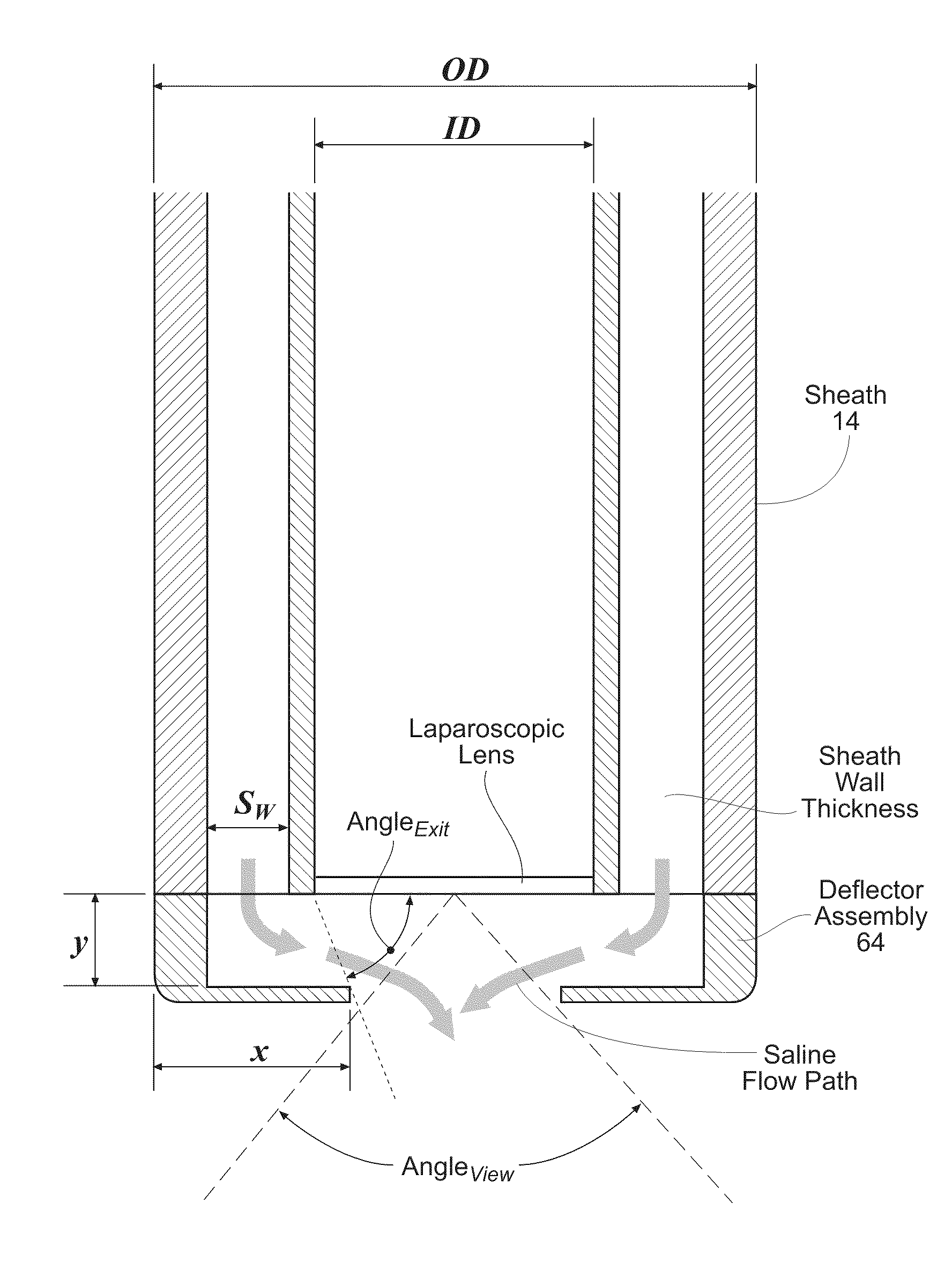
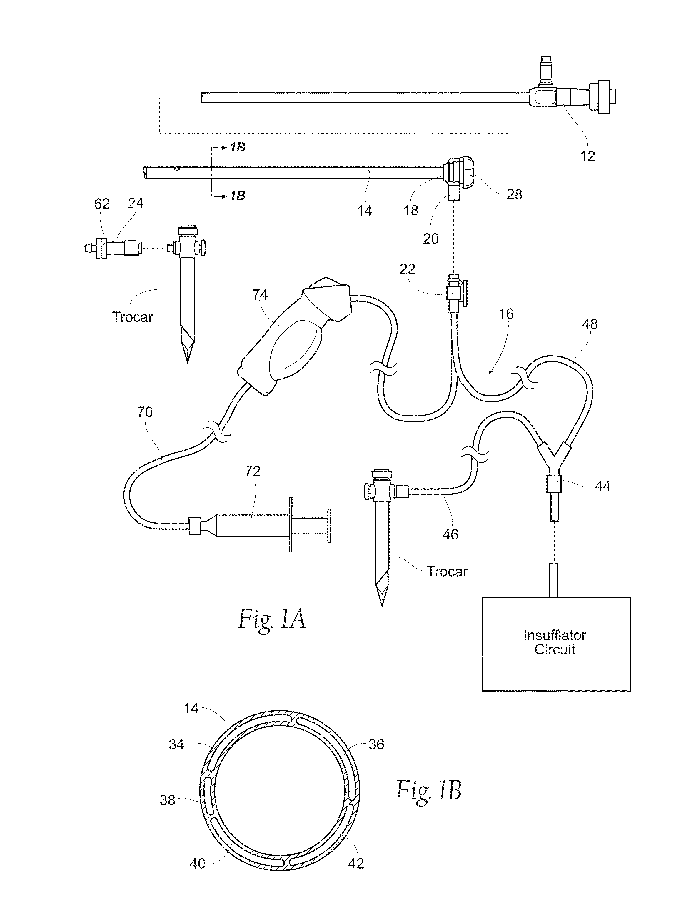
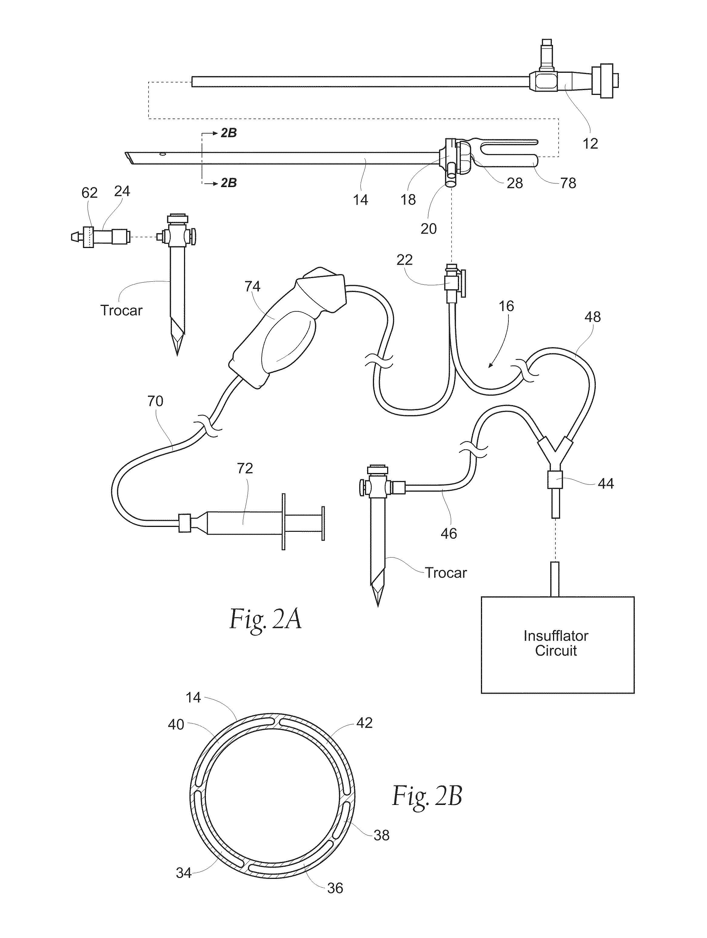
[0038]FIGS. 1A / 1B and FIG. 2A / 2B show a view optimizing assembly 10 for use in association with a state of the art laparoscope 12. In FIGS. 1A / 1B, the laparoscope 12 possesses at 0° (blunt) shaft tip In FIGS. 2A / 2B, the laparoscope possess an angle shaft tip (e.g., a 30° shaft tip or 45° shaft tip). The components of the view optimizing assembly 10 may be made from plastic materials (extruded and / or molded), but other suitable materials, such as metal or a composite material, or combinations thereof could be used.

[0039]As will be described in greater det...


PUM


Abstract

Systems and methods couple a self contained air processing or conveying component to a sheath that is sized and configured to receive a laparoscope including a laparoscopic lens providing visualization of an operating cavity. The air processing or conveying component comprises an air flow path having an inlet sized and configured for communication with a source of CO2 and an outlet. The air processing or conveying component includes a driven air moving component in communication with the air flow path sized and configured to continuously convey CO2 from the source through the air flow path to the outlet. The sheath coupled to the air processing or conveying component can include a lumen communicating with the outlet of the air processing or conveying mechanism for passing CO2 continuously conveyed by the driven air moving component across the laparoscopic lens to maintain visualization of the operating cavity. The sheath and self-contained air processing or conveying component can comprise an integrated assembly. The source of CO2 can comprise a laparoscopic access device for accessing the operating cavity insufflated with C02 by operation of an insufflator circuit. The driven air moving component continuously conveys CO2 from the operating cavity across the laparoscopic lens to maintain visualization of the operating cavity, independent of operation of the insufflations circuit.

Description

RELATED APPLICATION[0001]This application claims the benefit of U.S. Provisional Patent Application Ser. No. 61 / 335,712, filed Jan. 11, 2010, and entitled “Systems and Methods for Optimizing and Maintaining Visualization of a Surgical Field During the Use of Surgical Scopes,” which is incorporated herein by reference.FIELD OF THE INVENTION[0002]The invention generally relates to surgical scopes, and, more particularly, for optimizing and maintaining visualization of a surgical field when using a surgical scope, such as, e.g., a laparoscope.BACKGROUND OF THE INVENTION[0003]Minimally invasive surgical procedures utilizing surgical scopes are desirable because they often provide one or more of the following advantages: reduced blood loss; reduced post-operative patient discomfort; shortened recovery and hospitalization time; smaller incisions; and reduced exposure of internal organs to possible contaminants.[0004]Generally, minimally invasive surgeries utilize scopes, such as laparosco...

Claims


Application Information

Patent Timeline
IPC IPC(8): A61B1/00
CPCA61B1/00119A61B1/015A61B1/313A61B1/32A61B2017/3454A61B17/3474A61B19/34A61B2017/00296A61B17/3421A61B90/70A61B1/00163A61M13/006A61B1/00135A61B1/3132A61M39/08A61M2205/7536A61M2205/7545A61M2205/8206
Inventor POLL, WAYNE L.CRISAFULLI, CAROLINE M.DRACH, GREGORY P.
Owner FLOSHIELD INC
Learn More