Main shaft drive for machine tool

a technology of a machine tool and a main shaft, which is applied in the direction of manufacturing tools, mechanical equipment, precision positioning equipment, etc., can solve the problems of affecting the rotational speed of the driving side of the gear that engages each other, the rotational speed of the dd motor is not necessarily uniform, and the worm gear may be affected, so as to reduce the wear of the friction surface, maintain the magnitude of rotation resistance, and reduce the effect of oil film running ou

Inactive Publication Date: 2012-02-02
TSUDAKOMA KOGYO KK
View PDF8 Cites 7 Cited by
  • Summary
  • Abstract
  • Description
  • Claims
  • Application Information

AI Technical Summary

Benefits of technology

[0012]The present invention is achieved to overcome such problems, and its object is to make it possible to stably maintain the magnitude of rotational resistance applied to a main shaft by suppressing wear of a friction surface and a pressing surface in a main shaft drive in a machine tool.
[0015]According to the present invention having the above-described structure, the supply groove extends so as to surround the main shaft in the range where the friction surface and the pressing surface oppose each other, and the lubricant is supplied so as to be discharged from the discharge opening by passing the element extending in a direction of intersection with a direction along the circumference in which the rotational center of the main shaft serves as a center. Therefore, as the main shaft rotates, the element extending in a direction of intersection with a direction along the circumference and a range opposing the element move relative to each other. This makes it easier for the lubricant to reach a location within the range where the friction surface and the pressing surface oppose each other. This makes it possible to suppress running out of oil films at the friction surface and the pressing surface, to reduce wear of the friction surface and the pressing surface. Therefore, it is possible to maintain the magnitude of the rotation resistance applied to the main shaft by a rotation resistance applying device.
[0016]According to the one form of the present invention, a path of passage of the lubricant when the lubricant is supplied from the nozzle hole to the supply groove and is discharged from the discharge openings is divided into paths (portions) extending in different directions towards the two discharge openings that are positioned at respective sides of the corresponding nozzle hole when viewed from the corresponding nozzle hole. By this, even if the portion of the supply groove extending to one of the discharge openings is clogged with wear powder, it is possible to allow the lubricant supplied from the nozzle hole to the supply groove to pass through the other discharge opening. Therefore, it is possible to prevent the friction surface and the pressing surface from being raised by the pressure of the lubricant. Consequently, it is possible to maintain the rotation resistance applied to the main shaft by the rotation resistance applying device to a predetermined magnitude.

Problems solved by technology

However, the workpiece may be finished while continuously rotating the workpiece with the clamp device being set in an unclamped state.
However, since the control of the DD motor may not satisfactorily follow variations in the deviation of the rotation angle caused by the variation of the load received from the cutter, the rotation of the DD motor is not necessarily uniform, as a result of which pulsation may occur in the rotation of the main shaft.
When the drive transmission means such as a worm gear is used as driving means of the main shaft, backlash may exist in the worm gear, as a result of which the rotational speed of a driving side of gears that engage each other change due to the variation of the load received from the cutter.
In this case, driven-side (main-shaft side) gears rotate independently of the driving side within a backlash range due to inertia, thereby causing pulsation to occur in the rotation of the main shaft.
As a result, surface roughness of a finishing surface of a workpiece that is finished while rotating the circular table is increased.
When the pressing surface of the brake shoe and the friction surface of the rotating member are worn, states of the pressing surface and the friction surface change due to the wear.
As a result, as the wear progresses, pulsation occurs again in the rotation of the main shaft, thereby increasing the surface roughness of the finishing surface of the workpiece.
Therefore, it is difficult for the lubricant to reach a portion where the brake shoe press-contacts the rotating member due to, for example, the influence of the viscosity of the lubricant and the centrifugal force generated by the rotation of the rotating member.
Therefore, the pressing surface and the friction surface are not sufficiently lubricated, as a result of which oil films run out.
As a result, wear cannot be sufficiently suppressed.

Method used


Image

  • Main shaft drive for machine tool
  • Main shaft drive for machine tool
  • Main shaft drive for machine tool

Examples


Embodiment Construction

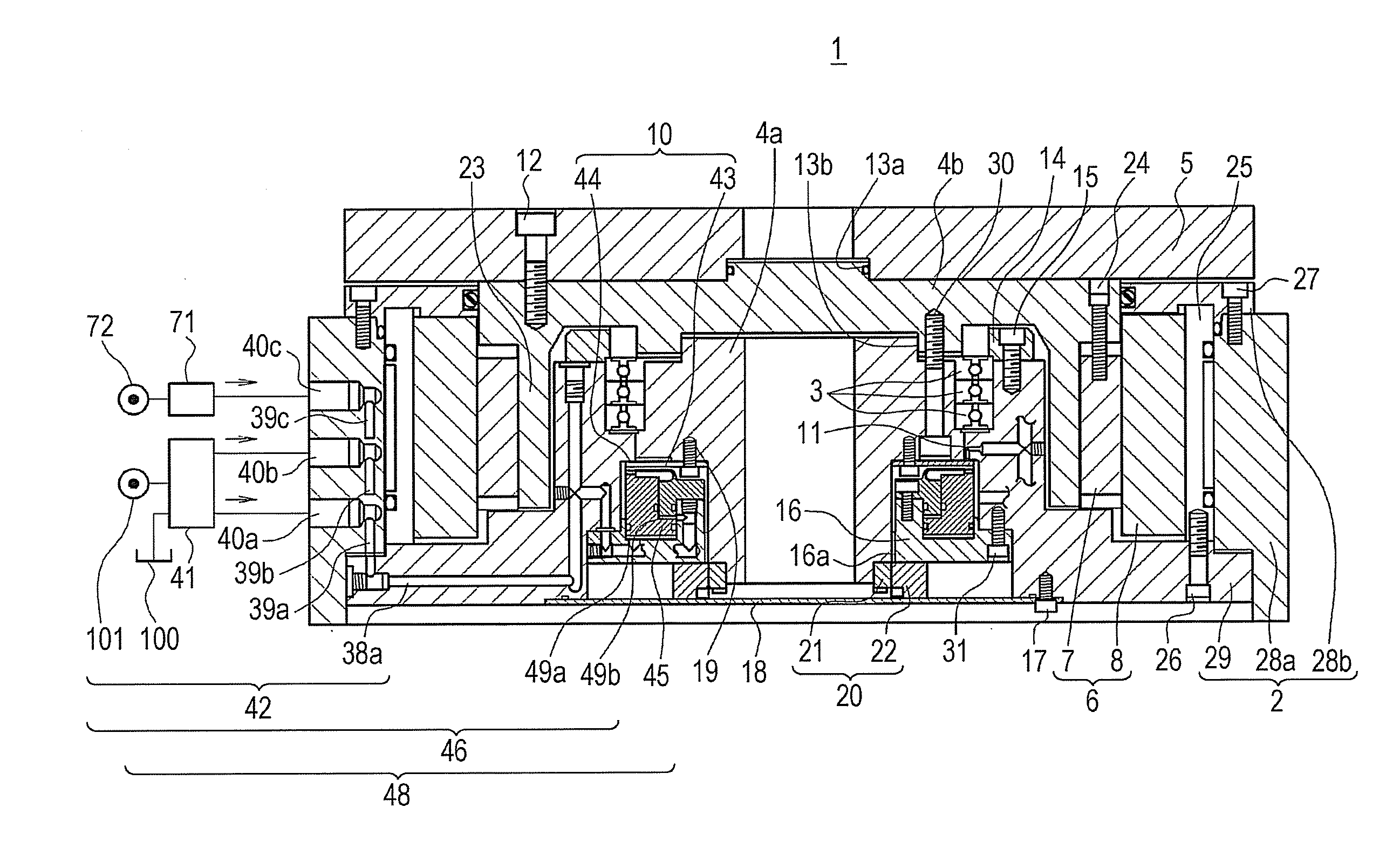
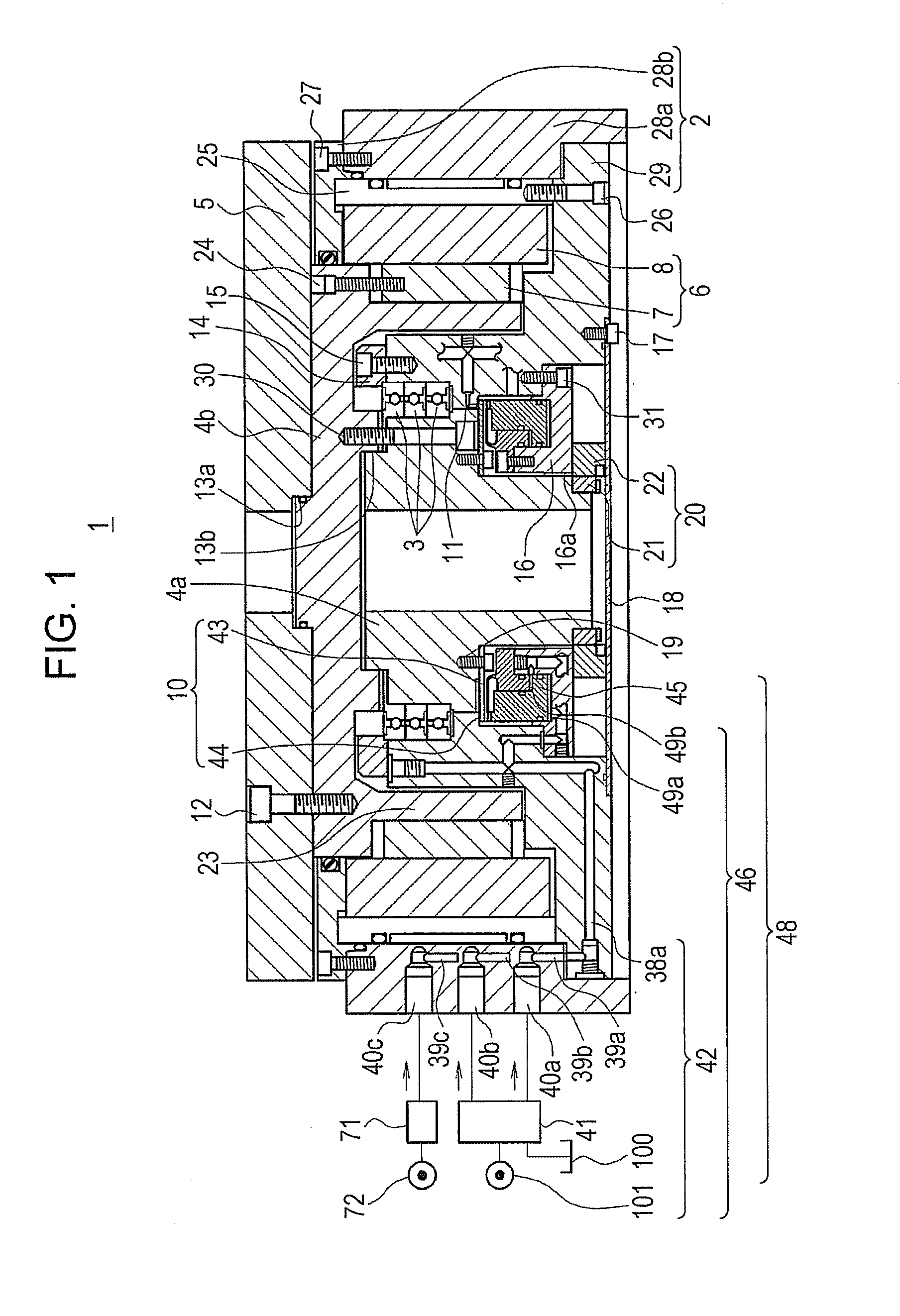
[0027]An embodiment of the present invention will hereunder be described with reference to FIGS. 1 to 3. In the embodiment, a rotating table device 1 is used as an exemplary main shaft drive for a machine tool including a rotation resistance applying device 10. The present invention is applied to the rotating table device. In the description below, “axial direction” refers to the direction of an axis of rotation of a main shaft 4a, and “radial direction” refers to a radial direction of the main shaft 4a and a circular table 5, that are concentrically disposed. In the axial direction, a circular-table-5 side of each member is defined as an upper side (upper end, upper surface), and the opposite side of each member is defined as the lower side (lower end, lower surface).

[0028]FIG. 1 shows the entire rotating table device 1 according to the embodiment. In the rotating table device 1, a jig and a workpiece to be processed are placed on a surface of the circular table 5 mounted to the ma...


PUM


Abstract

A main shaft drive includes a supply groove that opens to a friction surface, that extends so as to surround a main shaft within a contact range where the friction surface and a pressing surface oppose each other, and that includes an intersecting groove and a discharge opening. The intersecting groove extends in a direction of intersection with a circumference in which a rotational center of the main shaft is a center. The discharge opening is connected to a location that is outside the contact range. By opening a nozzle hole, used for supplying lubricant, towards the supply groove, as the main shaft rotates, four intersecting grooves move relative to the contact range, so that the lubricant is supplied to the four moved intersecting grooves. Therefore, the lubricant easily reaches a location within the contact range where the friction surface and the pressing surface oppose each other.

Description

BACKGROUND OF THE INVENTION[0001]1. Field of the Invention[0002]The present invention relates to a main shaft drive for a machine tool. More particularly, the present invention relates to a main shaft drive for a machine tool including a rotation-resistance applying device that applies rotation resistance to a main shaft by causing a pressing surface of a pressing member to press-contact a friction surface of a press member when the main shaft that is rotatably supported at a frame is rotationally driven.[0003]2. Description of the Related Art[0004]Hitherto, as a main shaft drive used in a machine tool, a rotation index table device is known. In the rotation index table device, a circular table on which a workpiece (object to be processed) is placed is secured to a main shaft, and the circular table is rotated by rotationally driving the main shaft. The rotation index table device is used for indexing an angular position of the circular table by rotationally driving the main shaft, ...

Claims


Application Information

Patent Timeline
Patent Type & Authority Applications(United States)
IPC IPC(8): F16D65/00
CPCB23Q16/105B23Q2220/004
Inventor TATSUDA, YOSHINORI
Owner TSUDAKOMA KOGYO KK
Why Eureka
Try Eureka