Conveyor device, conveyor chain as well as chain link

a conveyor chain and conveyor technology, applied in the direction of conveyors, transportation and packaging, etc., can solve the problems of high maintenance and repair costs, conveyor chains are not provided for circulating about deflection, and there is no possibility of integrating a power supply line, etc., to achieve simple and cost-effective, high stability and tightness, and protect against external effects. the effect of high leakage resistan

Active Publication Date: 2012-02-02
POLMAN ECKHARD
View PDF1 Cites 3 Cited by
  • Summary
  • Abstract
  • Description
  • Claims
  • Application Information

AI Technical Summary

Benefits of technology

[0013]Here, the power supply line is practically designed substantially tight in order to avoid a loss of the medium compressed air, gas, hydraulic fluid or the like as well as contamination and the ingress of interfering particles. Practically, the power supply line to this end extends in sections through the individual chain links, in other words is a channel or integrated hose or an integrated cable in the case of electric power formed in the chain link for example through bores or other hollow spaces. This embodiment can be simply and cost-effectively produced with high stability and tightness and is additionally low-maintenance. The power supply line, however, can also be designed as channel fitted to the chain links at least in sections, for example through a hose or a fitted cable.
[0014]Since preferably each chain link comprises a connecting point for the connection to a preceding chain link and a connecting point for the connection to a following chain link, the section of the power supply line can extend from the one to the other connecting point. This embodiment can be effected free of interruption and connecting point particularly in the interior of the chain link, as a result of which a highly leak proof tightness with protection against external effects is ensured.

Problems solved by technology

Disadvantageous with this known conveyor device are the extensive maintenance and repair.
However, such conveyor chains are not provided for circulating about deflection rollers and additionally have no possibility of integrating a power supply line.

Method used


Image

  • Conveyor device, conveyor chain as well as chain link
  • Conveyor device, conveyor chain as well as chain link
  • Conveyor device, conveyor chain as well as chain link

Examples


Embodiment Construction

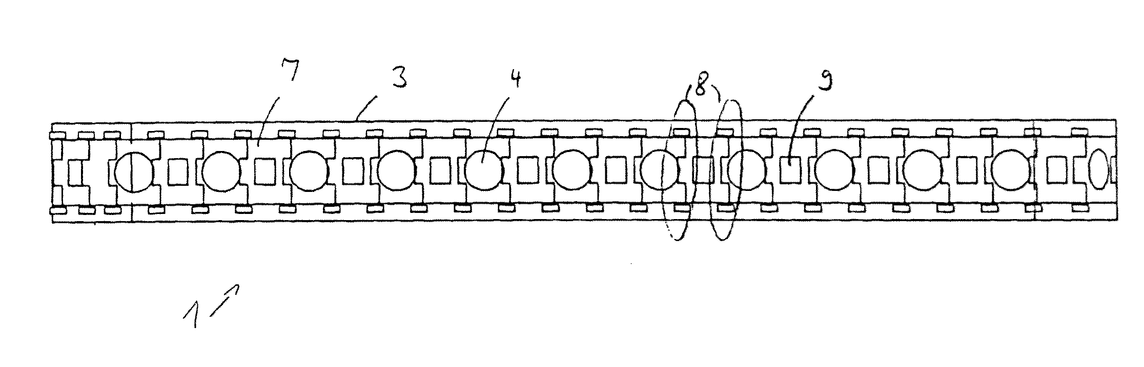
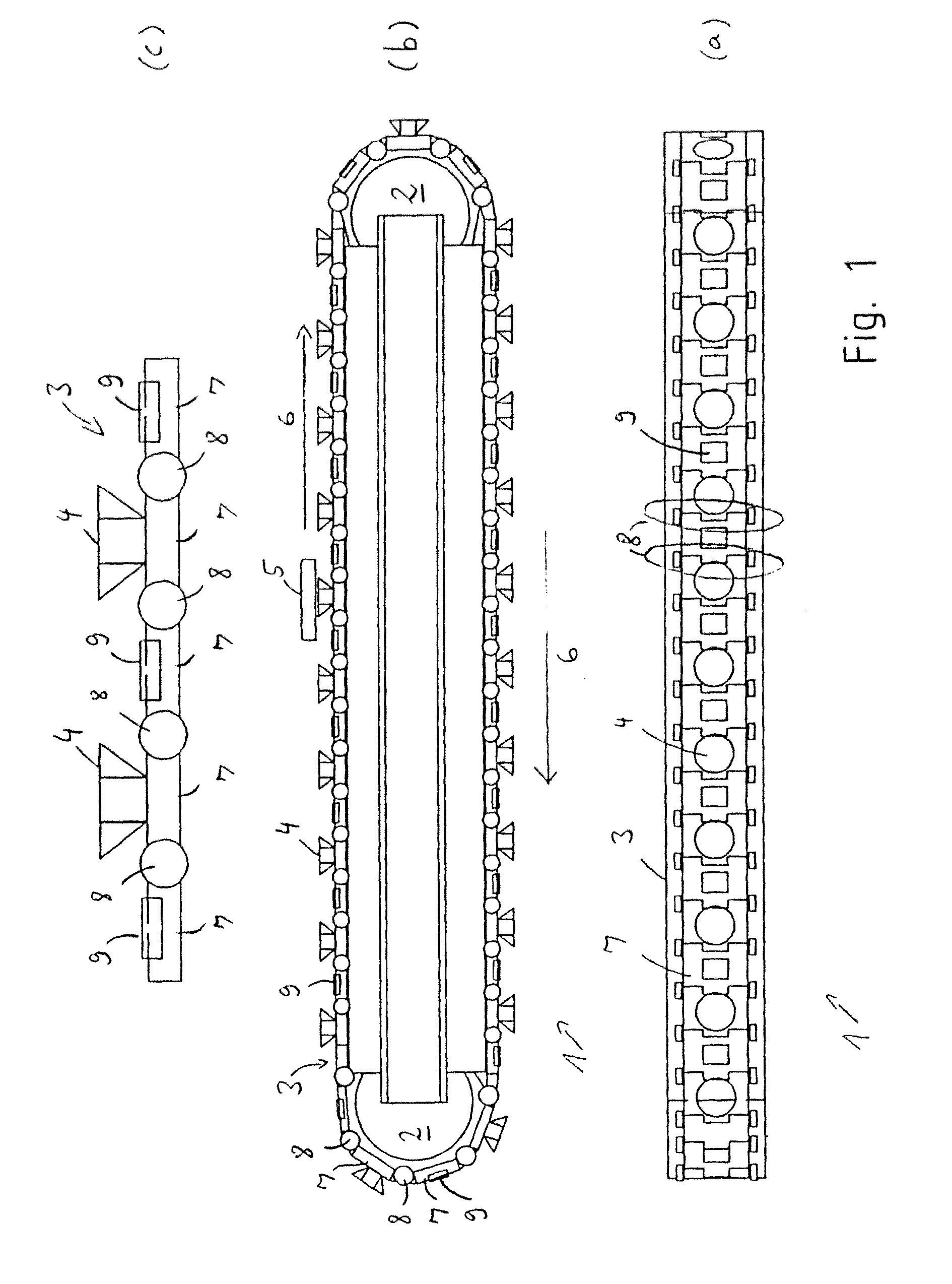
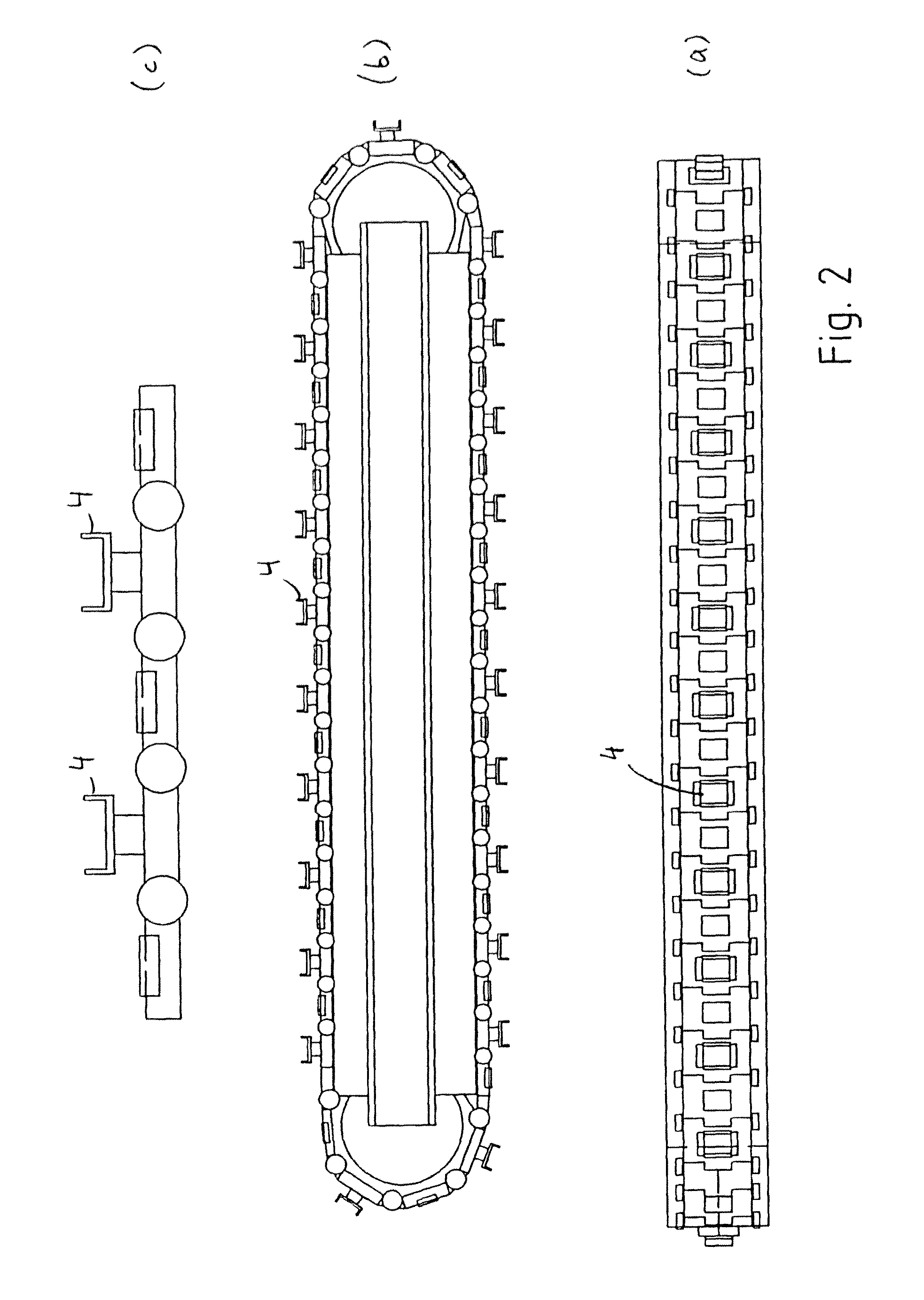
[0046]The conveyor device 1 shown in FIG. 1 comprises an endless conveyor element circulating in this case between two deflection rollers 2 in the form of a conveyor chain 3 with receiving devices 4 for conveying goods to be conveyed. The receiving devices 4 can receive work pieces 5 of which only one is exemplarily illustrated, conveying said work pieces along the conveying direction 6 in which the conveyor chain 3 circulates.

[0047]Conveying can be effected in a lying or suspended manner. Different work pieces 5 can be conveyed, for example circuit boards, metal plates, glass plates, window panes, automotive components, electronic components etc. The work pieces 5 need not be flat but can be shaped in any way.

[0048]The receiving devices 4 in the embodiment shown in FIG. 1 are represented as suction cups. These create a vacuum in order to firmly grasp the work pieces by suction. The work pieces 5 are picked up by the receiving devices 4 at suitable points, for example from a stack o...


PUM


Abstract

The invention relates to a conveyor device having an endless conveyor which revolves between deflection rollers and on which a receiving device for conveying goods to be conveyed is provided. The conveyor device also includes a power supply line. The conveyor element is a conveyor chain having chain links hinged together. Each link has a section of the power supply line, and the sections of adjacent chain links are coupled to each other.

Description

[0001]The invention relates to a conveyor device, a conveyor chain as well as a chain link according to the preamble of claims 1, 15 and 16 respectively.BACKGROUND OF THE INVENTION[0002]Known from WO 2008 / 104404 A2 is a conveyor device with an endless conveyor belt circulating between deflection rollers and to which a work piece receiving device is fastened, wherein a synchronously circulating separately designed endless power supply line is provided. Disadvantageous with this known conveyor device are the extensive maintenance and repair. Thus, upon a defect in the conveyor belt, the entire conveyor belt has to be replaced. This requires a complete disassembly of the conveyor device.[0003]Indeed, in the prior art, e.g. from DE 199 57 009 A1, conveyor devices are known in the form of endless conveyor chains consisting of chain links hinged together. However, such conveyor chains are not provided for circulating about deflection rollers and additionally have no possibility of integra...

Claims


Application Information

Patent Timeline
Patent Type & Authority Applications(United States)
IPC IPC(8): B65G17/12B65G17/38
CPCB65G17/46B65G17/323
Inventor POLMAN, ECKHARD
Owner POLMAN ECKHARD
Why Eureka
Try Eureka