Airbag apparatus

a technology of airbags and occupants, which is applied in the direction of pedestrian/occupant safety arrangements, vehicular safety arrangements, vehicle components, etc., can solve the problems of increasing the cost of airbags, occupants cannot be adequately protected from impact, etc., and achieves simple and inexpensive configuration, the effect of improving the characteristics of the load received

Active Publication Date: 2012-02-02
TOYODA GOSEI CO LTD
View PDF3 Cites 52 Cited by
  • Summary
  • Abstract
  • Description
  • Claims
  • Application Information

AI Technical Summary

Benefits of technology

[0011]An objective of the present invention is to provide an airbag apparatus that can improve characteristics of a load received by an occupant through an airbag with a simple and inexpensive configuration.

Problems solved by technology

As a result, sufficient protection of the occupant against the impact cannot be started before the load has reached the predetermined value.
However, it causes an increase in costs of the airbag apparatus.
Such problem occurs in the above-discussed side airbag apparatus as well as other types of airbag apparatuses.

Method used


Image

  • Airbag apparatus
  • Airbag apparatus
  • Airbag apparatus

Examples


first embodiment

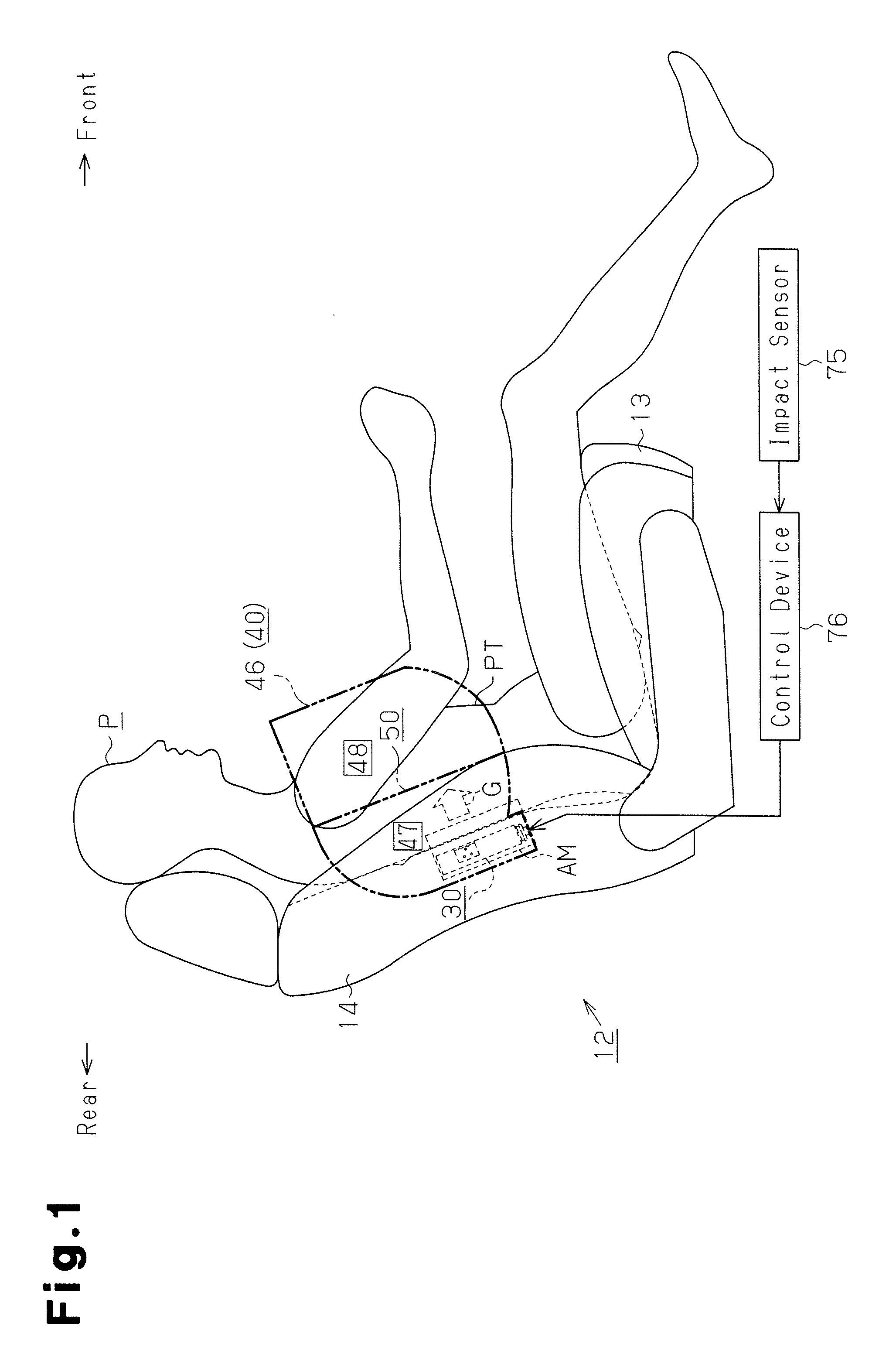
[0085]A first embodiment of the present invention, which is embodied as a vehicle side airbag apparatus, will be described below with reference to FIGS. 1 to 13.

[0086]In the following description, it is assumed that the forward direction of the vehicle is frontward and the backward direction of the vehicle is rearward. Also, in the following description, it is assumed that vertical means a vertical direction with respect to the vehicle, and left-right means a direction relative to the vehicle in the widthwise direction and corresponding to left-right directions while the vehicle moves frontward.

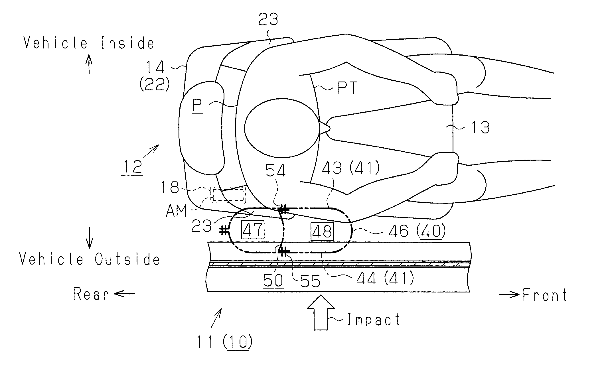
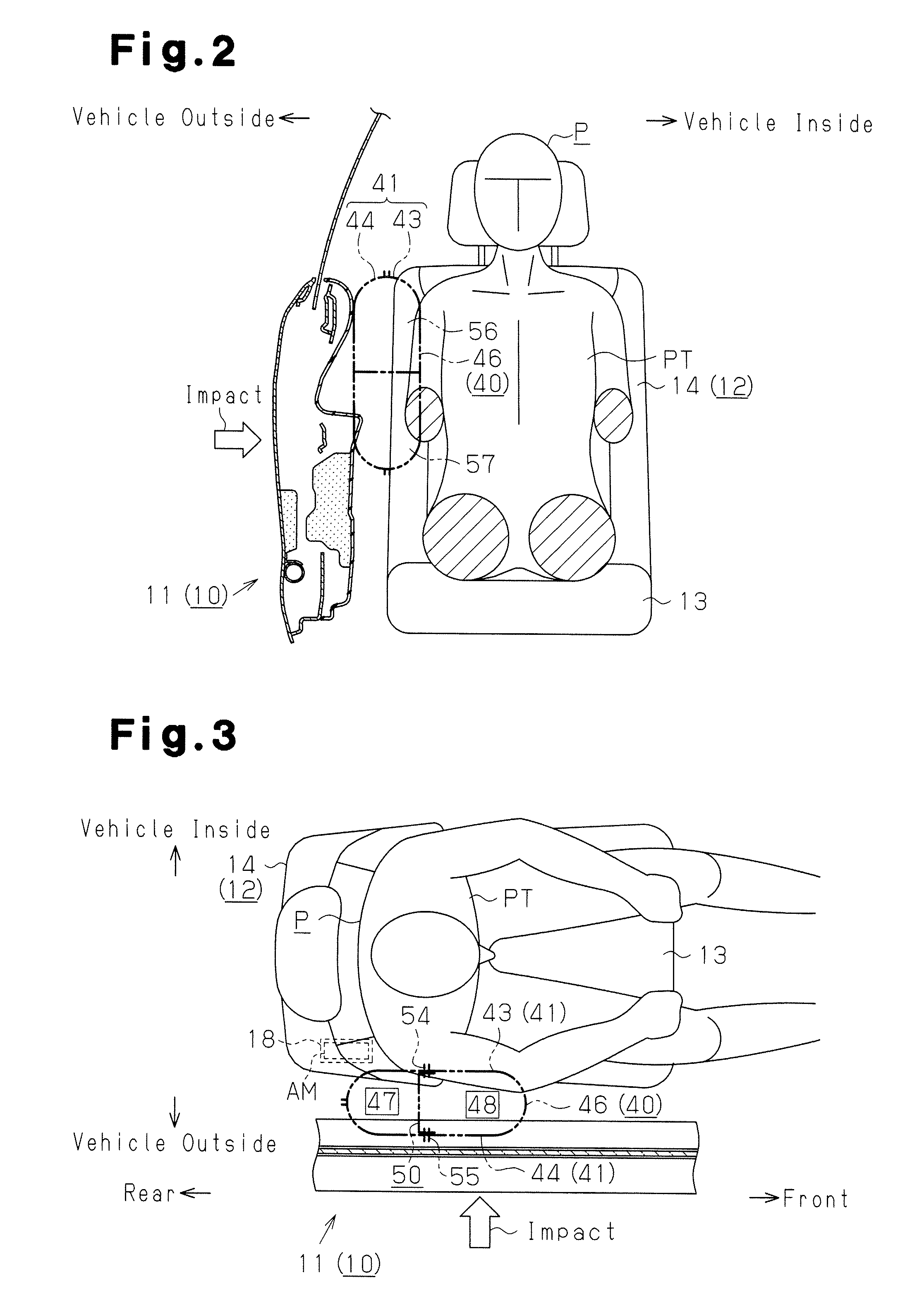
[0087]As shown in FIGS. 2 and 3, a vehicle seat 12 is disposed in the vicinity of the inner side (right side in FIG. 2, upper side in FIG. 3) of a body side portion 11 in a vehicle 10. Here, the body side portion 11 refers to a vehicle component disposed on the side of the vehicle 10, and mainly includes a door and a pillar. For example, the body side portion 11 corresponding to a front seat ...

second embodiment

[0176]Next, a second embodiment embodying the present invention will be described with reference to FIGS. 14 to 17.

[0177]The second embodiment is different from the first embodiment in that, as shown in FIGS. 14 to 16, the pair of overlapping portions 61 including the valve body portions 73, 74 are disposed in the downstream inflation portion 48 before inflation of the inflation portion 46. Thus, similar points and members to those in the first embodiment are given the same reference numerals and detailed description thereof is omitted. In FIG. 14, an area surrounded by a large circle X expressed by a chain line represents an enlargement of an area surrounded by a small circle X.

[0178]In this case, the overlapping portions 61 including the valve body portions 73, 74 behave differently as compared to the first embodiment.

[0179]Before supply of the inflation gas G to the inflation portion 46, the partition member 50 is folded in half such that the bend line 51 is disposed upstream of ...

third embodiment

[0194]Next, a third embodiment embodying the present invention will be described with reference to FIGS. 18 to 22.

[0195]In the third embodiment, as shown in FIGS. 18 to 20, the partition member 50 is folded in half along the bend line 51 extending in the longitudinal direction such that the opposing ends 52, 53 facing each other are close to each other. The partition member 50 is disposed in the inflation portion 46 in the uninflated and deployed state such that the bend line 51 is located downstream of the opposing ends 52, 53.

[0196]This other configuration is similar to that in the first embodiment. Thus, similar points and members to those in the first embodiment are given the same reference numerals and detailed description thereof is omitted. In FIG. 18, an area surrounded by a large circle Y expressed by a chain line represents an enlargement of an area surrounded by a small circle Y.

[0197]In this case, before supply of the inflation gas to the inflation portion 46, the partit...


PUM


Abstract

An inflation portion of an airbag, which is inflated by inflation gas, is partitioned into an upstream inflation portion and a downstream inflation portion via a partition member. When being tensioned in a planar manner, the partition member has a length in a longitudinal direction that is longer than a length in a transverse direction perpendicular to the longitudinal direction. A pressure regulating valve that is closed at an early stage of a supply period of the inflation gas to the inflation portion and is opened from the middle of the supply period includes a slit-like inner opening that is provided on the partition member and extends in the transverse direction and a pair of valve body portions that are provided around the inner opening and are selectively positioned close to and separated from each other.

Description

BACKGROUND OF THE INVENTION[0001]The present invention relates to an airbag apparatus that inflates an airbag when an impact is applied to a vehicle due to collision, thereby protecting an occupant against the impact.[0002]An airbag apparatus is effective as an apparatus for protecting the occupant against an impact applied to a vehicle due to collision. Such an airbag apparatus includes an airbag in the form of a bag and an inflator for supplying inflation gas into the airbag.[0003]One mode for such a type of airbag apparatus is a side airbag apparatus for protecting an occupant against, for example, impact from a side collision. In this side airbag apparatus, the foregoing airbag in a folded state and the inflator are incorporated into a seat back of a vehicle seat. In the side airbag apparatus, when an impact is applied to a member constituting a side part of the vehicle (body side portion), for example, a side door, from a side, the inflation gas is supplied from the inflator in...

Claims


Application Information

Patent Timeline
Patent Type & Authority Applications(United States)
IPC IPC(8): B60R21/16B60R21/26
CPCB60R21/233B60R21/2346B60R2021/0051B60R2021/23146B60R21/239B60R21/276B60R21/207B60R21/23138B60R2021/23324
Inventor SHIBAYAMA, KOJIHONDA, KENSAKUSATO, YUJIITO, MICHIYASUHOTTA, MASASHIAOKI, MASASHIYAMAMURA, DAISUKE
Owner TOYODA GOSEI CO LTD
Why Eureka
Try Eureka