

Compact Patch Antenna Array
- Summary
- Abstract
- Description
- Claims
- Application Information
AI Technical Summary
Benefits of technology
Problems solved by technology
Method used
Image

Examples
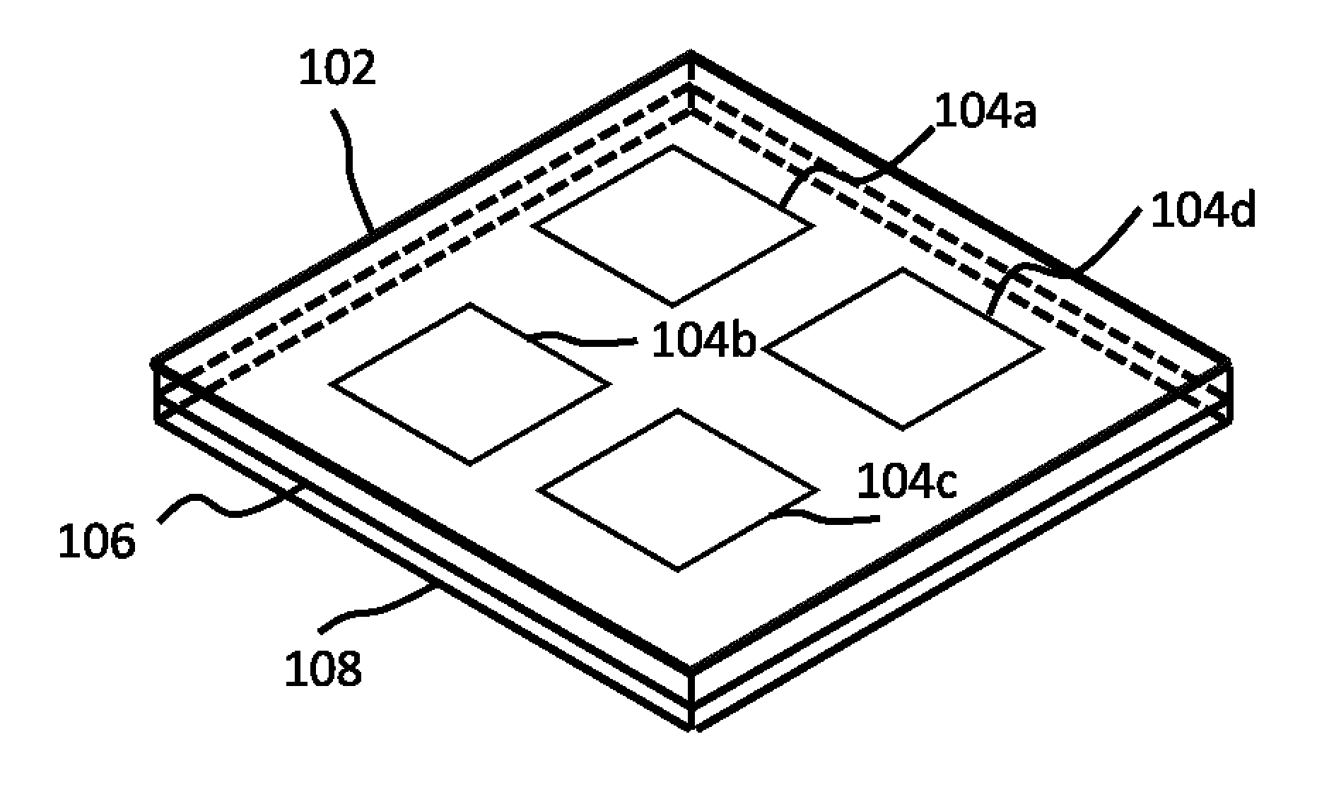
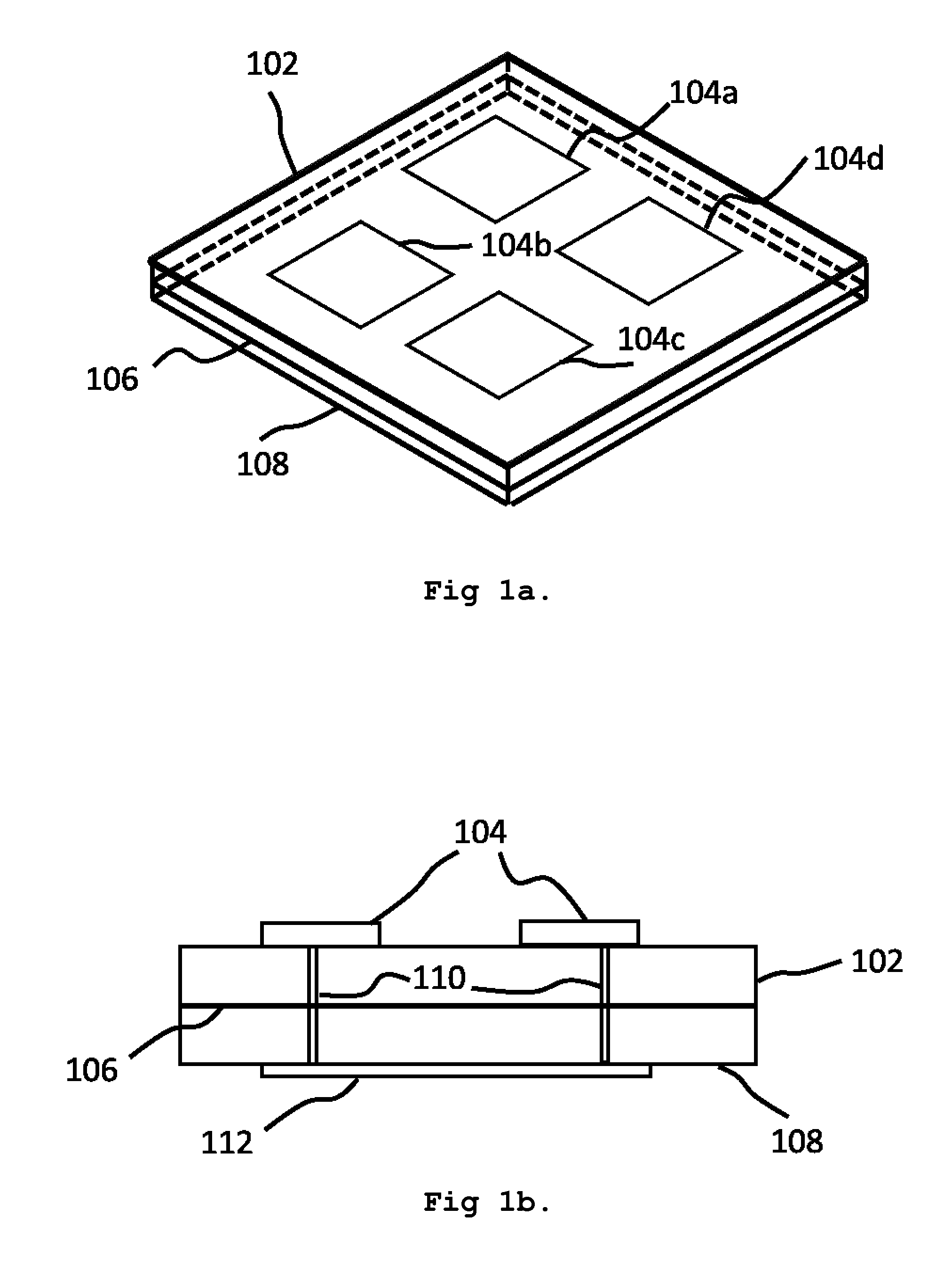
embodiment 1
Alternative Embodiment 1
[0030]Besides the embodiment described previously, another implementation of radiators are also useful. As shown in FIG. 3a and FIG. 3b, an example of a conformal array is presented. Again, number of elements is not restricted to 4 but any number more than one.
[0031]In this embodiment, all antenna elements are implemented on an exemplary curve structure, not limited to the shown curve, instead on any curve that is not planar. This embodiment is very useful when ultra-compact capability is required. For example, with this design, aircraft antenna systems would not have to be implemented separately. It could be part of the body. Further applications can be found in missiles, as they have a strict requirement for ultra-compact arrays while maintaining high levels of power output and gain. With this structure, part of the body could be used as an antenna, which is very space efficient.
embodiment 2
Alternative Embodiment 2
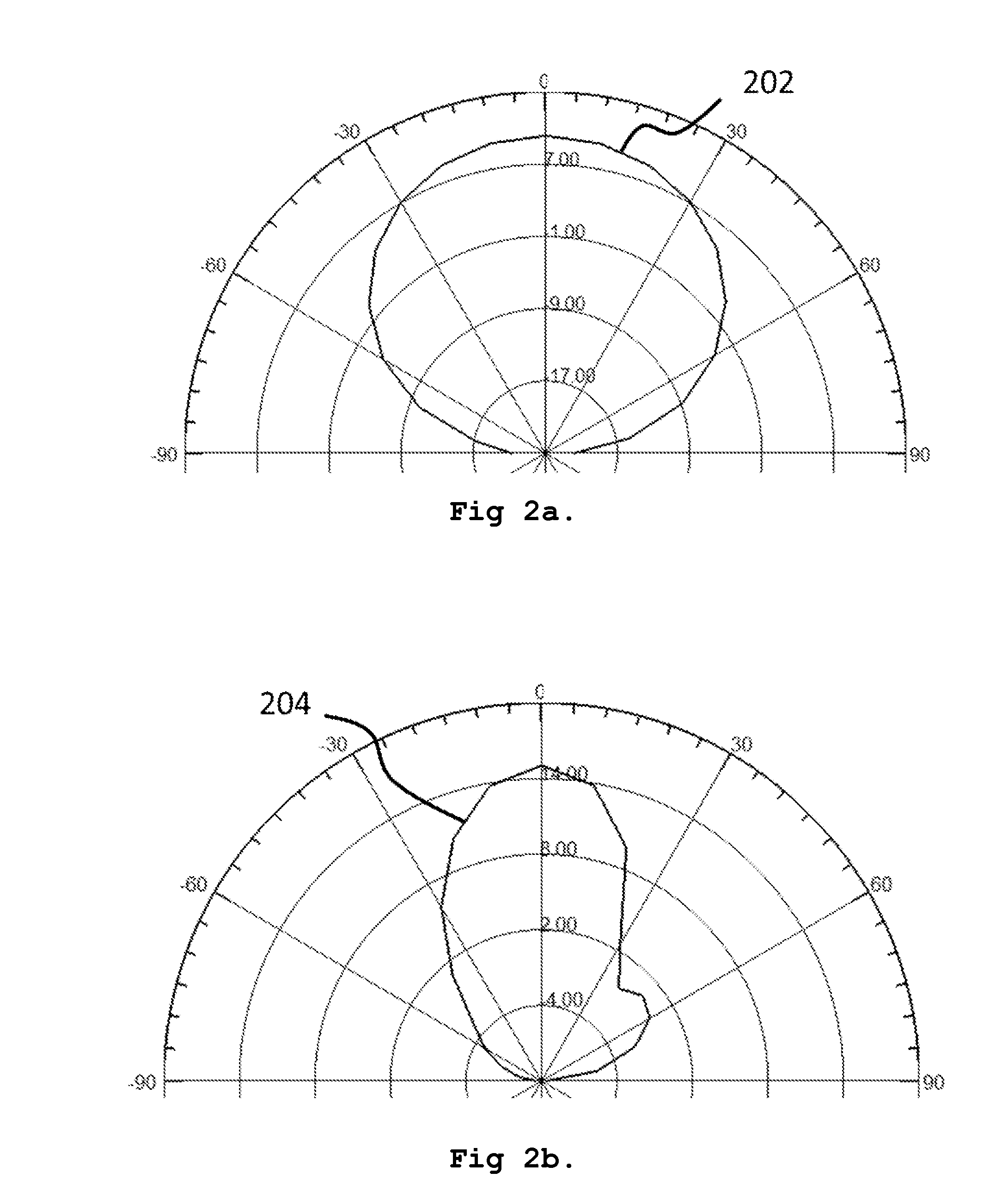
[0032]Another useful alternation of this design is shown in FIG. 5a and FIG. 5b. In this embodiment, each antenna element 502a,b,c,d is facing a different direction. In such a way, because radiations on the side are enhanced significantly that rather than concentrating all power on bore sight, the radiation pattern becomes flat and wide.
[0033]Radiation pattern of a non-planar embodiment 602 in FIG. 6 shows an exemplary performance of this embodiment. Radiation pattern of a non-planar embodiment 602 is a plane cut at θ=0°. There are several points on this curve to be noticed. Gain at θ=30° is −4 dB. Gain at θ=60° is −0.5 dB. Gain at θ=90° is −0.8 dB. Thus this embodiment forms a relatively flat radiation pattern on its side with minimum reception on bore sight, θ=0°.
[0034]In global navigation satellite systems (GNSS), including GPS, Galileo, Glonass and Beidou, satellites are for the majority of the time never right above users at the θ=0° angle. Due to the an...
embodiment 3
Alternative Embodiment 3
[0037]Apart from different implementations on antenna array, the feeding network can be implemented in various ways. Previously discussed feeding networks and antenna arrays are in the form of microstrips. Alternatively, in another embodiment the feeding network can also be strip line as shown in FIG. 4. In FIG. 4 the feeding network 112, instead of being mounted on the surface of dielectric 108, the feeding network 112 is placed within dielectric 108. This integration of two elements into a single space serves to increase redundancy and save some space.
[0038]Alternatively, instead of directly exiting the radiators, the feeding network 112 can excite radiator 104 by coupling, which means the feeding network 112 doesn't necessarily directly contact the radiator 104.
PUM
 Abstract
Description
Claims
Application Information