
Radio communication system, centralized station, control station apparatus, radio base station and coordinated transmission method

a radio communication system and control station technology, applied in wireless communication services, electrical equipment, wireless communication services, etc., can solve problems such as performance degradation, sinr (signal-to-interference and noise power ratio) reduction, and interference from neighboring cells or neighboring sectors. to avoid interference not only

Inactive Publication Date: 2012-02-02
NTT DOCOMO INC
View PDF7 Cites 23 Cited by
  • Summary
  • Abstract
  • Description
  • Claims
  • Application Information

AI Technical Summary

Benefits of technology

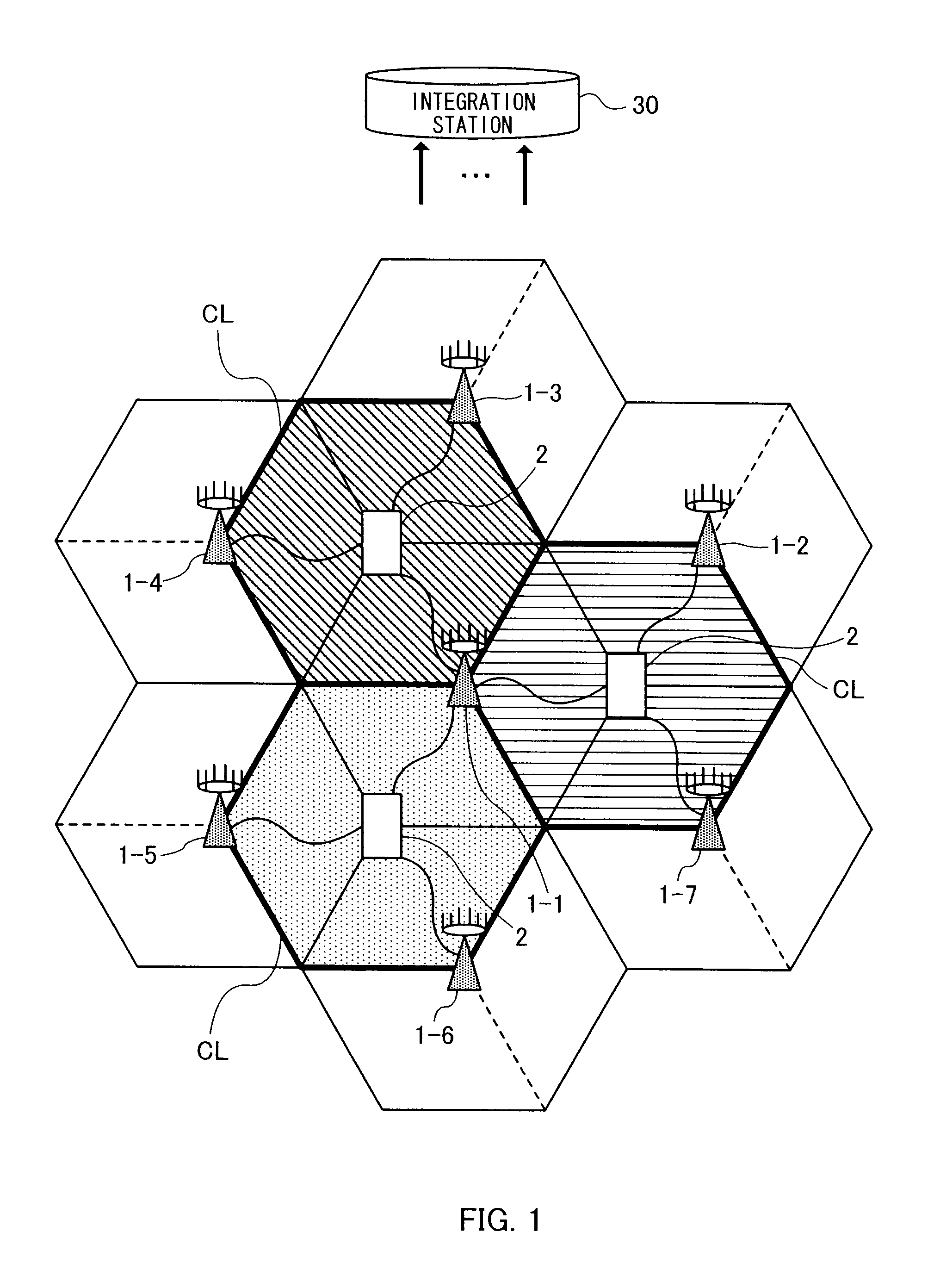
The present invention provides a method for avoiding inter-cluster interference in a radio communication system with multiple radio base stations. The method involves determining a cluster pattern for each cluster of neighboring cells, which defines a directional pattern of which directional beams emitted from the radio base stations face each other for each identical frequency block. The cluster patterns are assigned to the radio base stations in units of a cluster composed of neighboring cells, and data signals are transmitted between the radio base stations in a coordinated manner within the assigned cluster using multi-user MIMO precoding. The technical effect of the invention is to reduce inter-cluster interference and improve the overall performance of the radio communication system.

Problems solved by technology

When one-cell frequency reuse is used in a cellular scheme using this OFDMA scheme, interference from a neighboring cell or neighboring sector is a dominant reason for performance degradation.
To be more specific, as interference power from the neighboring cell or neighboring sector increases, an SINR (Signal-to-Interference and Noise power Ratio) decreases, and it is therefore difficult to obtain benefits thereof when performing MIMO (Multiple-Input Multiple-Output) transmission.
However, the aforementioned interference avoidance technique can avoid interference in the coordinated cluster, but has a problem that the technique is unable to avoid interference between coordinated clusters.

Method used


Image

  • Radio communication system, centralized station, control station apparatus, radio base station and coordinated transmission method
  • Radio communication system, centralized station, control station apparatus, radio base station and coordinated transmission method
  • Radio communication system, centralized station, control station apparatus, radio base station and coordinated transmission method

Examples


embodiment 1

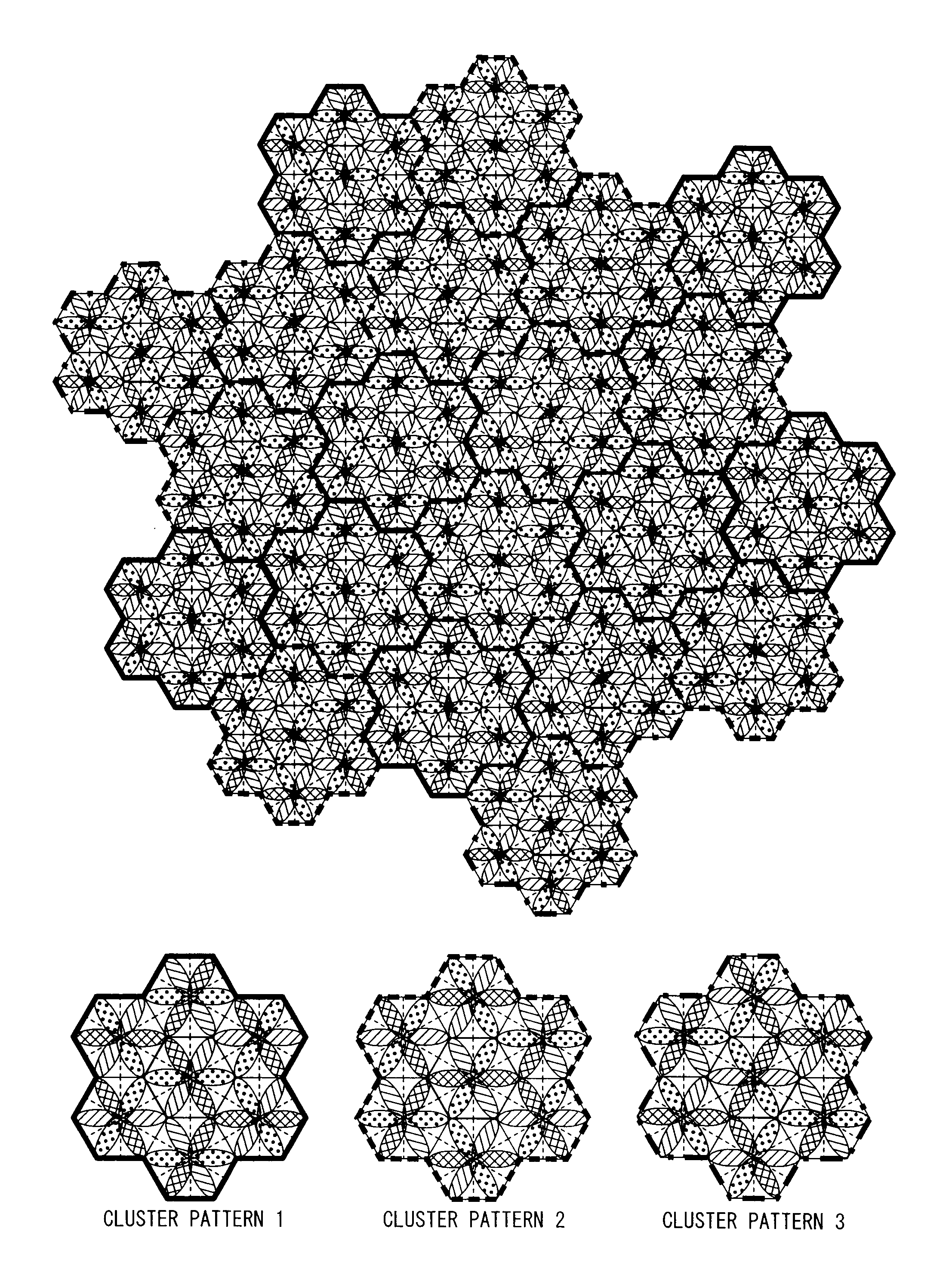
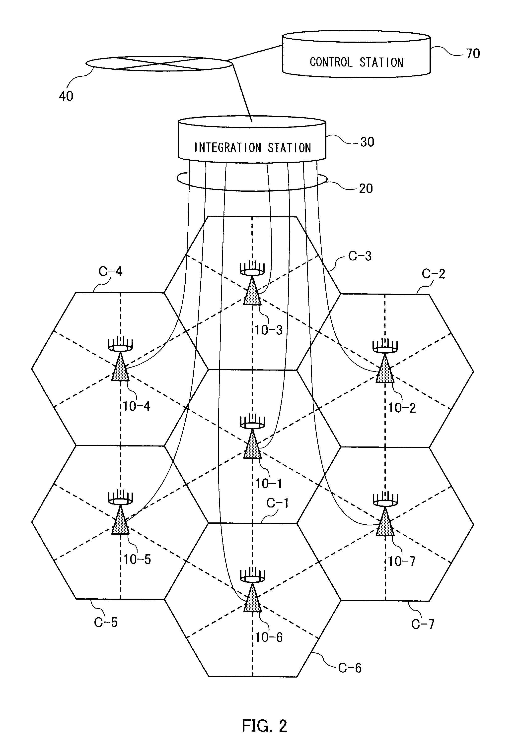
[0055]FIG. 8 is a system configuration diagram of the radio communication system according to present Embodiment 1 and shows up to a control station 70 that manages centralized stations 30 arranged in cluster units. However, all clusters shown in FIG. 8 show a state in which only the same cluster pattern shown in FIG. 7 is repeatedly applied. FIG. 8 shows inter-cluster interference when only the same cluster pattern is repeatedly applied. The plurality of radio base stations 10-1 to 10-7 forming their respective clusters are connected to the same centralized station 30. The centralized station 30 applies the cluster pattern shown in FIG. 7 to the radio base stations 10-1 to 10-7 forming the cluster under the control thereof, uses a precoding method for multiuser MIMO transmission and thereby orthogonalizes the space in the coordinated cluster CL.

[0056]However, when attention is focused on between the cluster pattern units (hereinafter, simply referred to as “between clusters” or “cl...

embodiment 2

[0098]FIG. 21 shows a function block of each radio base station in a radio communication system according to

[0099]In the radio communication system of present Embodiment 2, each radio base station is provided with a precoding function for MIMO transmission processing instead of each radio base station receiving precoded transmission data for MIMO transmission processing from the centralized station. The radio communication system is composed of a plurality of radio base stations 10 (first radio base station 10-1 to M-th radio base station 10-M) having the same configuration.

[0100]The radio base station 10 is provided with a modulation section 33, a precoding section 34 and a transmitting section 35. These components have the same functions as the respective function elements in the aforementioned centralized station 30. The radio base station 10 forms a beam for each frequency block according to a directional pattern determined based on cluster patterns that can avoid interference f...


PUM


Abstract

The radio communication system of the present invention is provided with a cluster pattern determining section 61 that determines the assignment of each cluster pattern to each cluster so as to suppress inter-cluster interference with other neighboring clusters less than or equal to a predetermined value, the cluster pattern is defining a directional pattern of which directional beams emitted from the respective radio base stations face each other for each identical frequency block between neighboring sectors in a cluster composed of neighboring cells, the each cluster pattern being in different combinations of directional patterns and frequency blocks.

Description

CROSS REFERENCE TO RELATED APPLICATION[0001]This application is based upon and claims the benefit of priority from the prior Japanese Patent Application No. 2010-169762, filed on Jul. 28, 2010; the entire contents of which are incorporated herein by reference.BACKGROUND OF THE INVENTION[0002]1. Field of the invention[0003]The present invention relates to a radio communication system, centralized station, control station apparatus, radio base station and coordinated transmission method when transmitting a signal to a radio terminal by coordinating a plurality of radio base stations.[0004]2. Description of the Related Art[0005]Cellular-based mobile radio communication systems are required to decrease the frequency reuse as much as possible to improve area spectral efficiency. For example, a third-generation cellular scheme using a CDMA (Code Division Multiple Access) scheme realizes one-cell frequency reuse (i.e., the rate at which the same frequency can be used in the network=1) whic...

Claims


Application Information

Patent Timeline
Patent Type & Authority Applications(United States)
IPC IPC(8): H04W72/04
CPCH04W16/10H04W16/28H04W16/12
Inventor BENJEBBOUR, ANASSOKUMURA, YUKIHIKOOHWATARI, YUSUKE
Owner NTT DOCOMO INC
Learn More