Image Measurement Device, Method For Image Measurement, And Computer Readable Medium Storing A Program For Image Measurement

a technology of image measurement and program, which is applied in the direction of image analysis, image enhancement, instruments, etc., can solve the problems of difficult identification of workpieces by users, and difficult identification of measurement results by users, so as to facilitate identification of relative positional relation and easy identification of measurement results

Active Publication Date: 2012-02-02
KEYENCE
View PDF2 Cites 14 Cited by
  • Summary
  • Abstract
  • Description
  • Claims
  • Application Information

AI Technical Summary

Benefits of technology

[0018]According to the image measurement device, the method for image measurement, and the program for the image measurement device of the present invention, when the measurement result is displayed over the workpiece image, the result of the pass or fail determination of the workpiece is displayed. Therefore, as compared to the case in which the size value of each portion to be measured for each workpiece is displayed, it is possible, for the plurality of workpieces, to easily recognize relative positional relation and easily identify the measurement result. Especially, since the pass or fail determination of the portion to be measured for the selected workpiece is displayed, for the desired workpiece, it is possible to identify the pass or fail determination of each workpiece and to switch to the display state in which the pass or fail of each portion to be measured can be identified. Further, the result of the pass or fail determination of the determination site for the selected workpiece is displayed. Therefore, it is possible to identify the pass or fail determination of each workpiece and to switch to the display state in which the pass or fail of each determination site can be identified for the desired workpiece.

Problems solved by technology

However, in the conventional image measurement device, it is hard to recognize relative position between the workpieces from the workpiece image for plurality of the workpieces placed on the movable stage, because visibility under the image measurement device is narrow.
Therefore, there is a difficulty for an user to identify which workpiece a measurement result of the workpiece image have been measured from.
However, if the measured sizes are displayed, it becomes difficult for an user to identify the measurement results.

Method used


Image

  • Image Measurement Device, Method For Image Measurement, And Computer Readable Medium Storing A Program For Image Measurement
  • Image Measurement Device, Method For Image Measurement, And Computer Readable Medium Storing A Program For Image Measurement
  • Image Measurement Device, Method For Image Measurement, And Computer Readable Medium Storing A Program For Image Measurement

Examples


first embodiment

Image Measurement Device

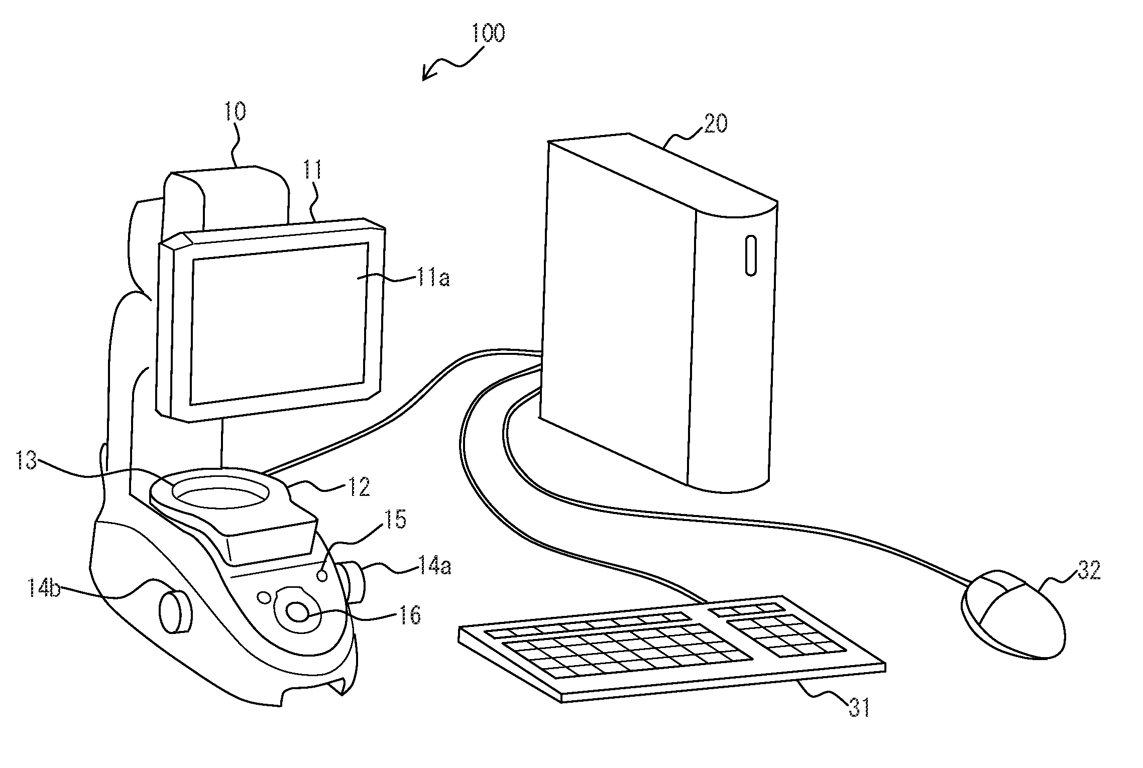
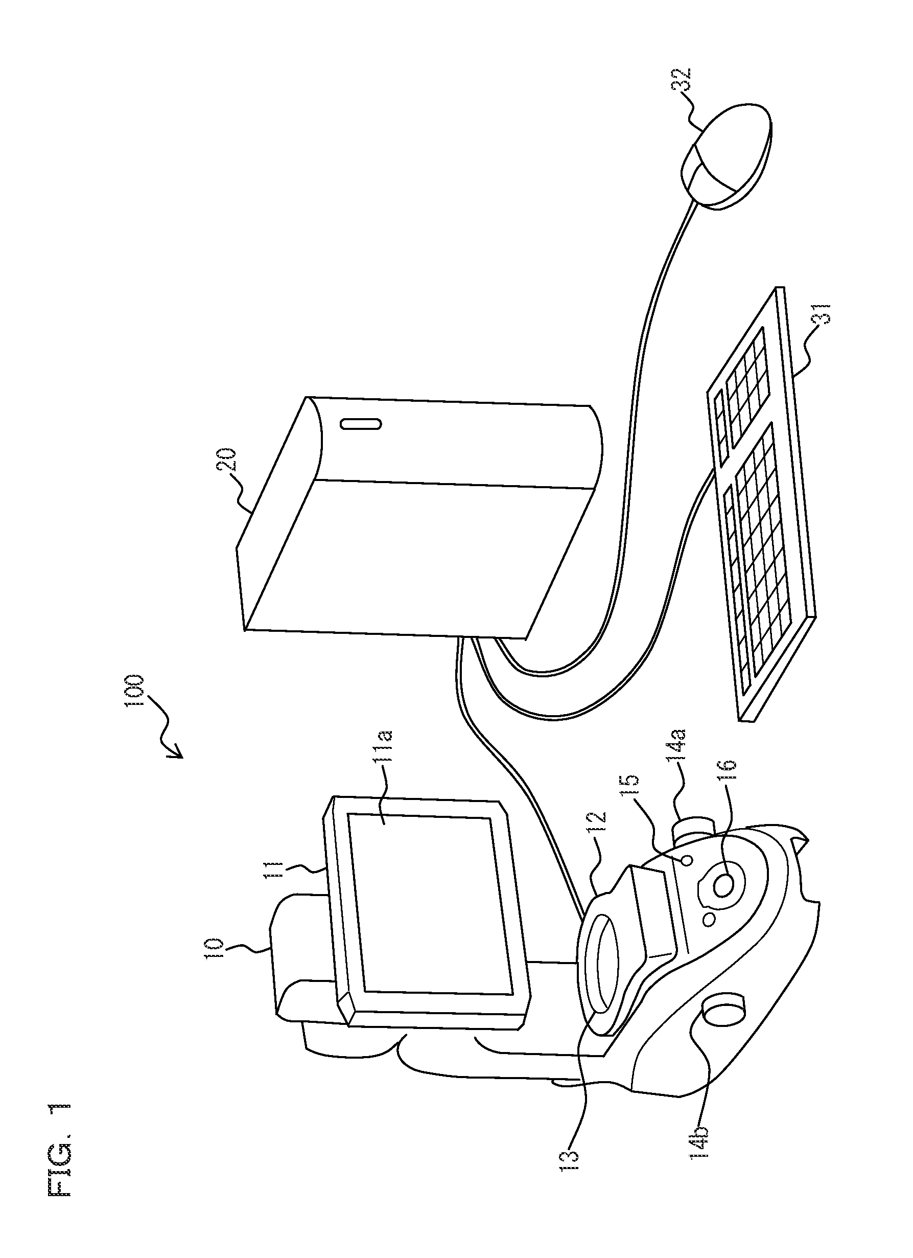
[0032]FIG. 1 is a perspective view showing one example of a configuration of an image measurement device 100 according to a first embodiment of the present invention. The image measurement device 100 is an image measuring instrument configured to pick up images of a plurality of workpieces placed in a detection area 13 on a movable stage 12 at different imaging magnifications and analyze the picked-up images, thereby automatically measuring a size of each workpiece. The image measurement device 100 is provided with a measuring unit 10, a control unit 20, a keyboard 31, and a mouse 32. Each workpiece is an object to be measured whose shape and size are measured.

[0033]The measuring unit 10 is an optical unit configured to irradiate each workpiece with detection light, and receives transmitted or reflected light, thereby generating a picked-up image. The measuring unit 10 is provided with a display 11, the movable stage 12, an XY position adjustment knob 14a, a ...

second embodiment

[0085]The first embodiment has described the case in which the result of the pass-fail determination for each workpiece is displayed in the first display state, and, when any of the workpieces is selected, the size values of the selected workpiece are displayed in the second display state in which the pass or fail of the size value can be identified for each portion to be measured. By contrast, this embodiment describes a case in which the portions to be measured of the workpiece are categorized into groups and the pass-fail determination is performed for each group including the plurality of portions to be measured.

[0086]FIG. 10 is a block diagram showing an example of a configuration of the control unit 20 of the image measurement device 100 according to the second embodiment of the present invention. The control unit 20 in this embodiment is different from the control unit 20 shown in FIG. 8 in that a determination site selection section 28 is provided.

[0087]The measurement confi...


PUM


Abstract

An image measurement device capable of recognizing a relative position and easily identifying a measurement result is provided, the device including: a measurement configuration data storage section that holds characteristic amount information, information for portions to be measured, and setting value information; a placement state detection section that detects a position and a posture of each workpiece; an edge detection section that detects an edge of portions to be measured; a pass-fail determination section that calculates size values of the portions to be measured and performs pass-fail determination of the portions to be measured and the workpiece; a measurement result display section that displays a result of the pass-fail determination of the workpiece over the workpiece image; and a workpiece selection section for selecting any of the workpieces. The measurement result display section displays the result of the pass-fail determination for the portions to be measured of the selected workpiece.

Description

CROSS-REFERENCE TO RELATED APPLICATIONS[0001]The present application claims foreign priority based on Japanese Patent Application No. 2010-170711, filed Jul. 29, 2010, the contents of which is incorporated herein by reference.BACKGROUND OF THE INVENTION[0002]1. Field of the Invention[0003]The present invention relates to an image measurement device, a method for image measurement, and a computer readable medium storing a program for an image measurement device. Particularly, the present invention relates to an improvement of the image measurement device for measuring the size of the workpiece by detecting edges within the workpiece image obtained thereby.[0004]2. Description of the Related Art[0005]Generally, the image measurement device is a device for measuring the size of the workpiece based on the edge position of the workpiece image (Japanese patent publication No. 2009-300124, No. 2009-300125, No. 2010-019667). As usual, the workpiece is placed on a movable stage which can be ...

Claims


Application Information

Patent Timeline
Patent Type & Authority Applications(United States)
IPC IPC(8): G06K9/48
CPCG01B9/04G06T2207/30164G06T7/0006G01B11/02
Inventor NARUSE, TAKASHI
Owner KEYENCE
Why Eureka
Try Eureka