Restrictor Clip

a technology of restrictors and clips, applied in the field of restrictor clips, can solve the problems of increased tendency to buckling along the inside edge, buckling and other detrimental events, and achieving the effect of uniform force distribution

Active Publication Date: 2012-02-09
AMMERAAL BELTECH MODULAR
View PDF5 Cites 4 Cited by
  • Summary
  • Abstract
  • Description
  • Claims
  • Application Information

AI Technical Summary

Benefits of technology

[0005]It is therefore an object of the present invention to avoid these prob

Problems solved by technology

In practice this causes wobbling and bending especially of the inside portion of the belt and at the same time causes tension in the outside of the belt.
As the force on the inside of the conveyor belt is substantially larger than the distributed force along the o

Method used


Image

  • Restrictor Clip
  • Restrictor Clip
  • Restrictor Clip

Examples


Embodiment Construction

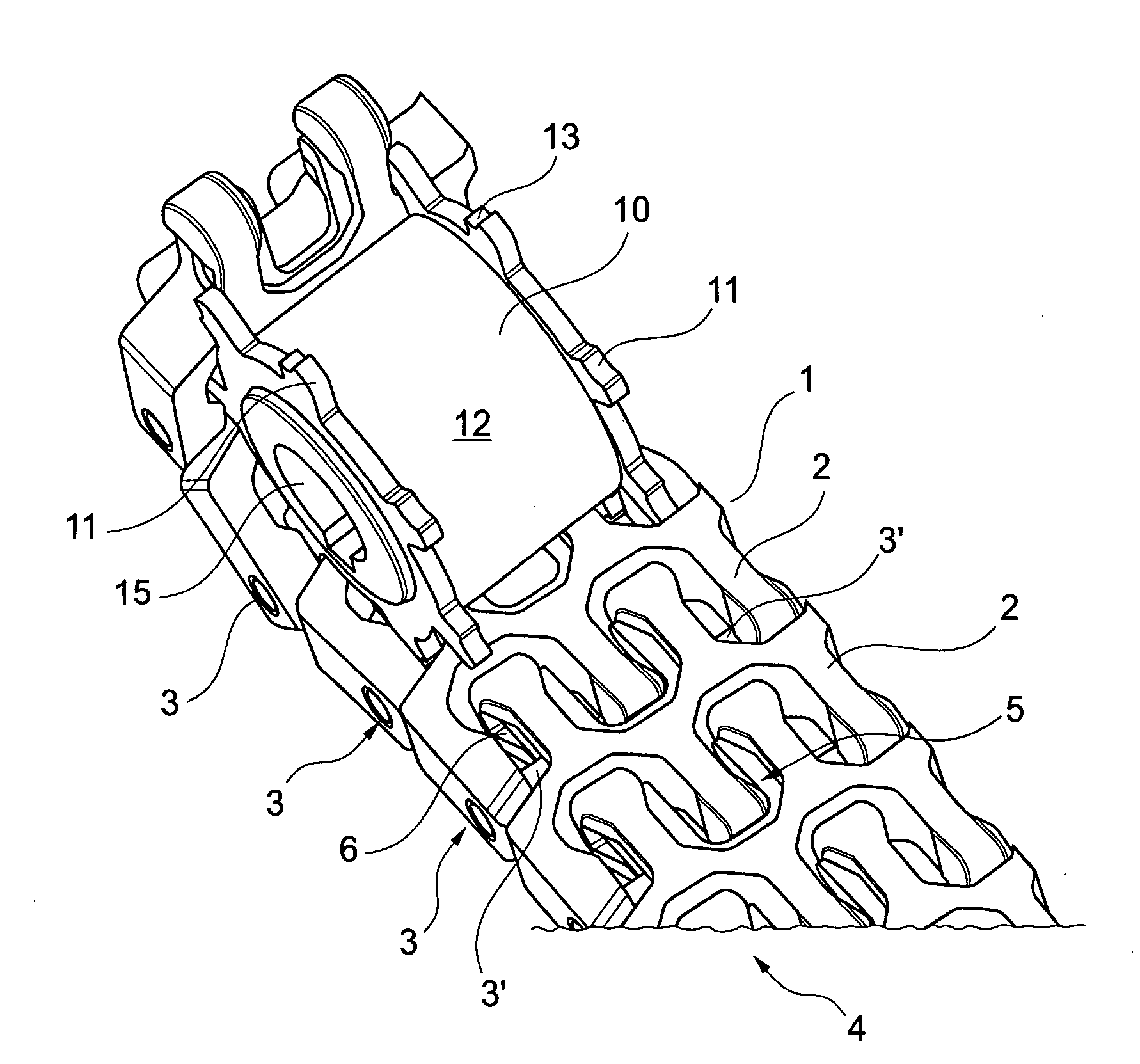
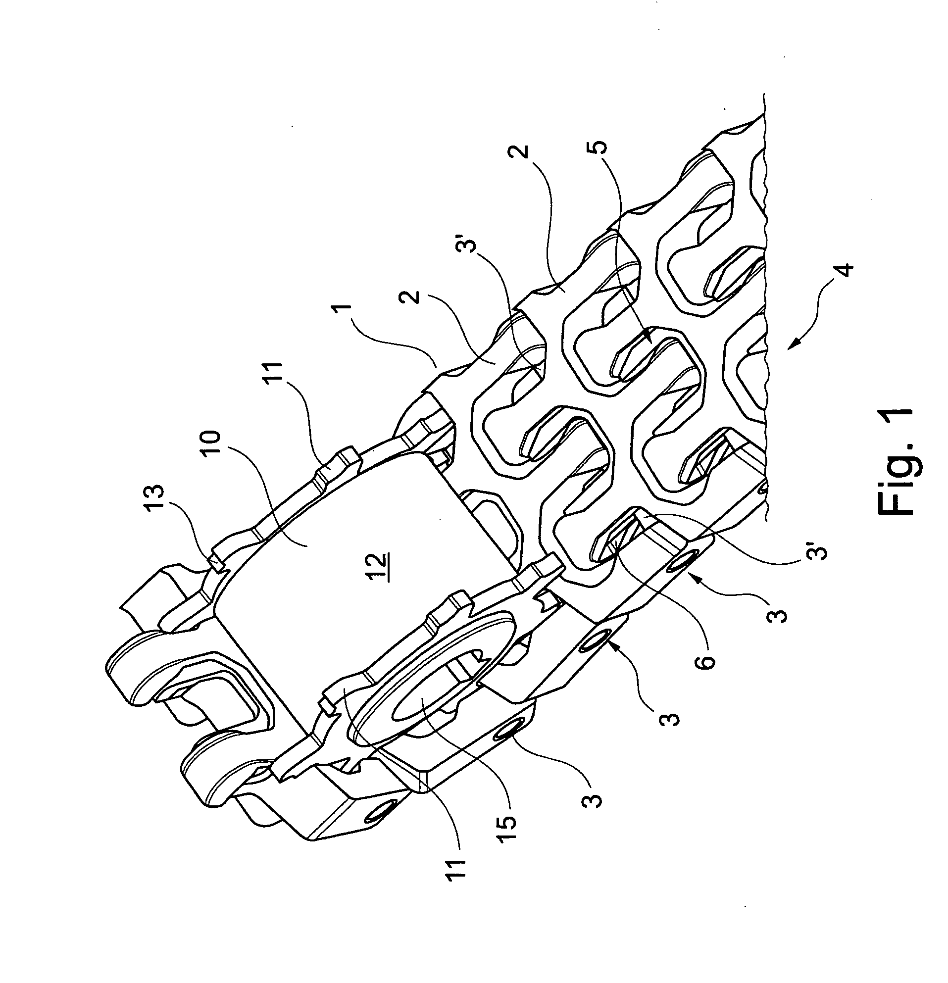
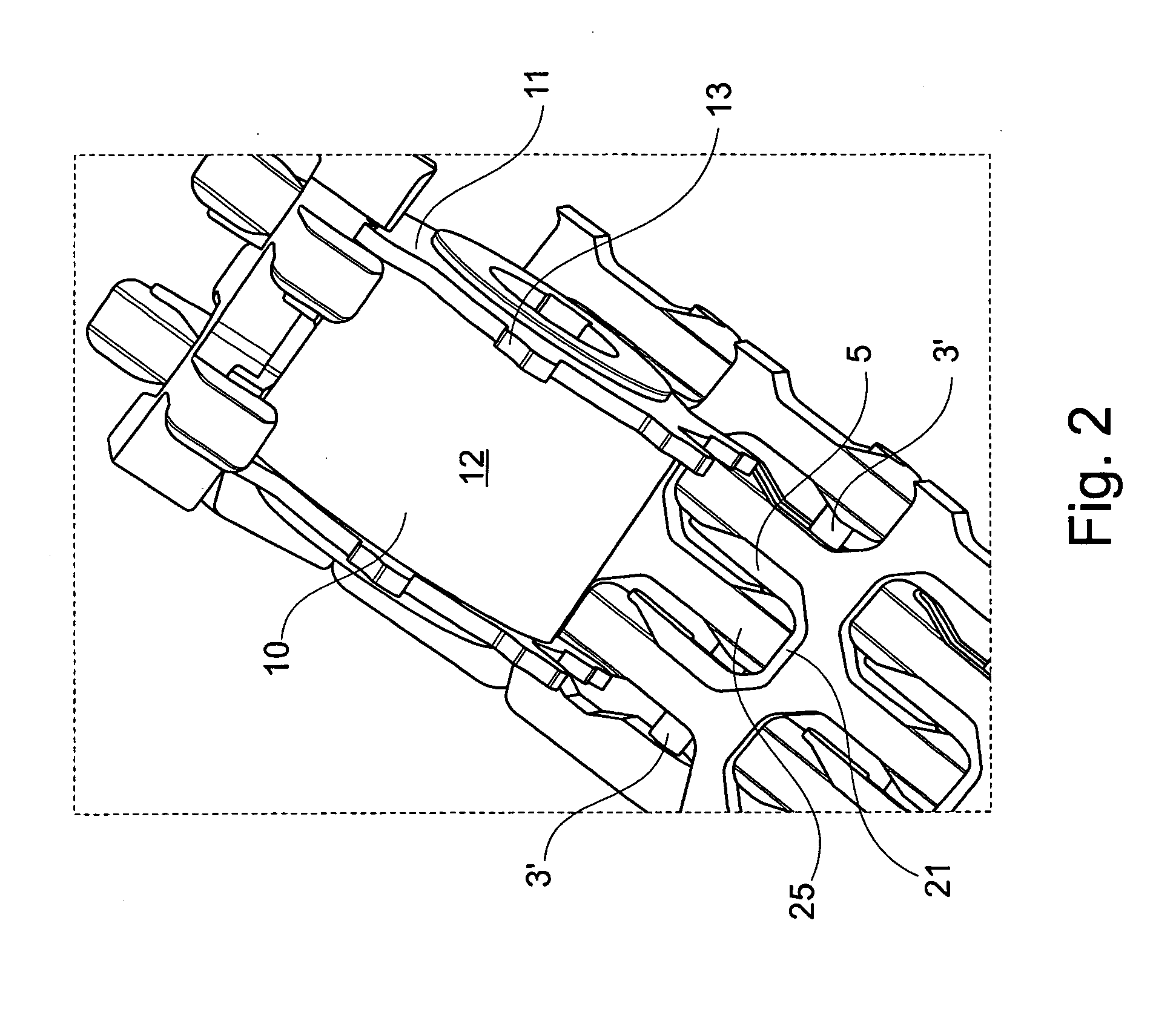
[0006]This is achieved by providing a restrictor clip, for use with modular conveyor belt links, where said belt links each has forwards and rearwards projecting eye parts, where said forward and rearward eye parts are offset, whereby it is possible to intercalate eye parts from one belt link between eye parts of an adjacent belt link, where the eye parts are provided with lateral apertures, such that as the eye parts overlap, a through-going aperture is provided, whereby a connecting rod may be inserted through overlapping apertures, thereby hingely connecting adjacent belt links, and where said apertures are oval, said aperture having a first longer axis being the longest cross distance in the aperture, and a second shorter axis, being the shortest cross distance in the aperture, and where said clip has a general U-shape, said U having two legs connected with a bridge portion in one end, and free ends in the opposite end, where in the free ends of the U, projecting members are pro...


PUM

PropertyMeasurementUnit
Radiusaaaaaaaaaa
Distanceaaaaaaaaaa

Abstract

Conveyor belts are made from modular links having offset forward and rearward projecting eye parts to intercalate eye parts from one belt link between eye parts with oval lateral apertures. Connecting rods inserted through aligned apertures hingedly connect adjacent links. Clips restrict lateral turning of the belt links. Clips have general U-shapes with two legs, a bridge portion end, and opposite free ends. Projecting members at the free ends have lengths parallel to the legs and smaller than the lengths of the apertures in the belt links in which the clip is to be installed, and have heights equivalent to or smaller than the heights of the aperture in the belt link in which the clip is to be installed. The lateral distance between the two legs of the U, is larger than the lateral extent of an eye part in the belt link in which the clip is installed.

Description

[0001]This application claims the benefit of Danish Application No. PA 2010 00294 filed Apr. 8, 2010, which is hereby incorporated by reference in its entirety as if fully set forth herein.FIELD OF THE INVENTION[0002]The present invention relates to a restrictor clip for use in conveyor belts constructed by connecting a plurality of substantially identical modular beltings particularly for use where the conveyor belt is used in a spiral device such as for example a spiral freezer or spiral oven.BACKGROUND OF THE INVENTION[0003]In a spiral oven or freezer the conveyor belt in the forward run follows a well-defined spiral path such that the conveyor belt turns around a central tower / drum on the inside and on the outside the belt is limited by a guide rail or similar device. This causes the side flex conveyor belt to be exposed to tension along the outside edge of the belt whereas the inside edge of the belt which is lying against the drum is substantially slack, i.e. is not exposed to...

Claims


Application Information

Patent Timeline
IPC IPC(8): B65G17/38B23P11/00B65G21/18
CPCB65G17/086Y10T29/49826B65G2207/12
Inventor BUTER, GERM
Owner AMMERAAL BELTECH MODULAR
Why Eureka
Try Eureka