Magnetic-controlled actuator with auto-locking function for joints of manipulation arm

a technology of magnetic control and actuator, which is applied in the direction of dynamo-electric brake control, mechanical energy handling, dynamo-electric brake/clutch, etc., can solve the problems of low efficiency of motors and the inability of rotors to produce holding torque, and achieve high cogging torque for actuators

Inactive Publication Date: 2012-02-09
DELTA ELECTRONICS INC
View PDF9 Cites 10 Cited by
  • Summary
  • Abstract
  • Description
  • Claims
  • Application Information

AI Technical Summary

Benefits of technology

[0019]Therefore, a cogging effect, which is produced due to interaction of the permanent magnets between the outer-layer mover and the outer-layer stator, is automatically produces a high cogging torque for the actuator. Thus the actuator provides a sufficient locking force to lock the non-stationary inner-layer mover when a power failure occurs.

Problems solved by technology

The rotor can not produce holding torque when the winding is not excited due to the absence of the magnetic force produced from the stator winding.
For example, a large-volume motor is required, an overheating issue occurs due to the over current, and the motor has a low efficiency.

Method used


Image

  • Magnetic-controlled actuator with auto-locking function for joints of manipulation arm
  • Magnetic-controlled actuator with auto-locking function for joints of manipulation arm
  • Magnetic-controlled actuator with auto-locking function for joints of manipulation arm

Examples


Embodiment Construction

[0032]Reference will now be made to the drawing figures to describe the present invention in detail.

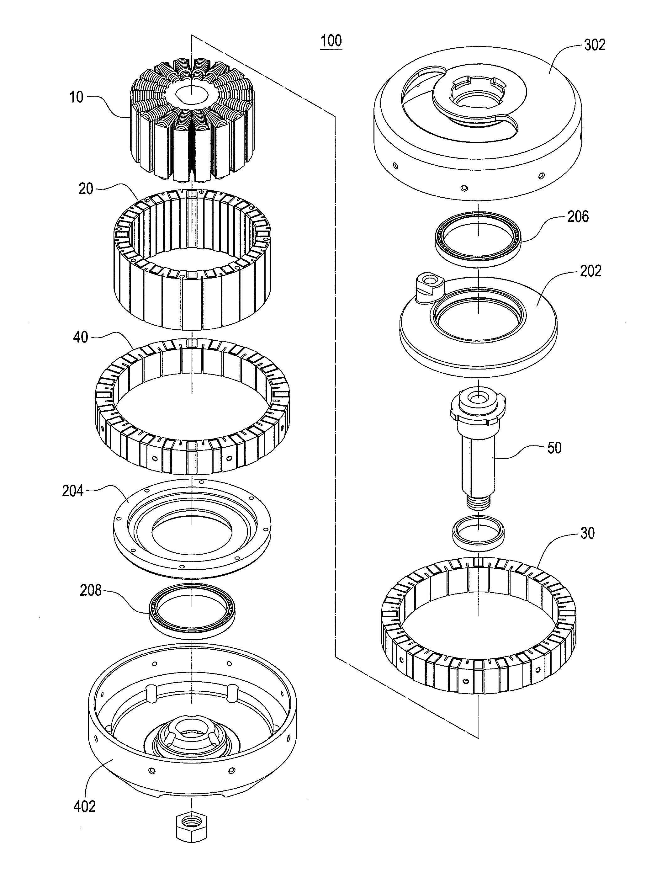
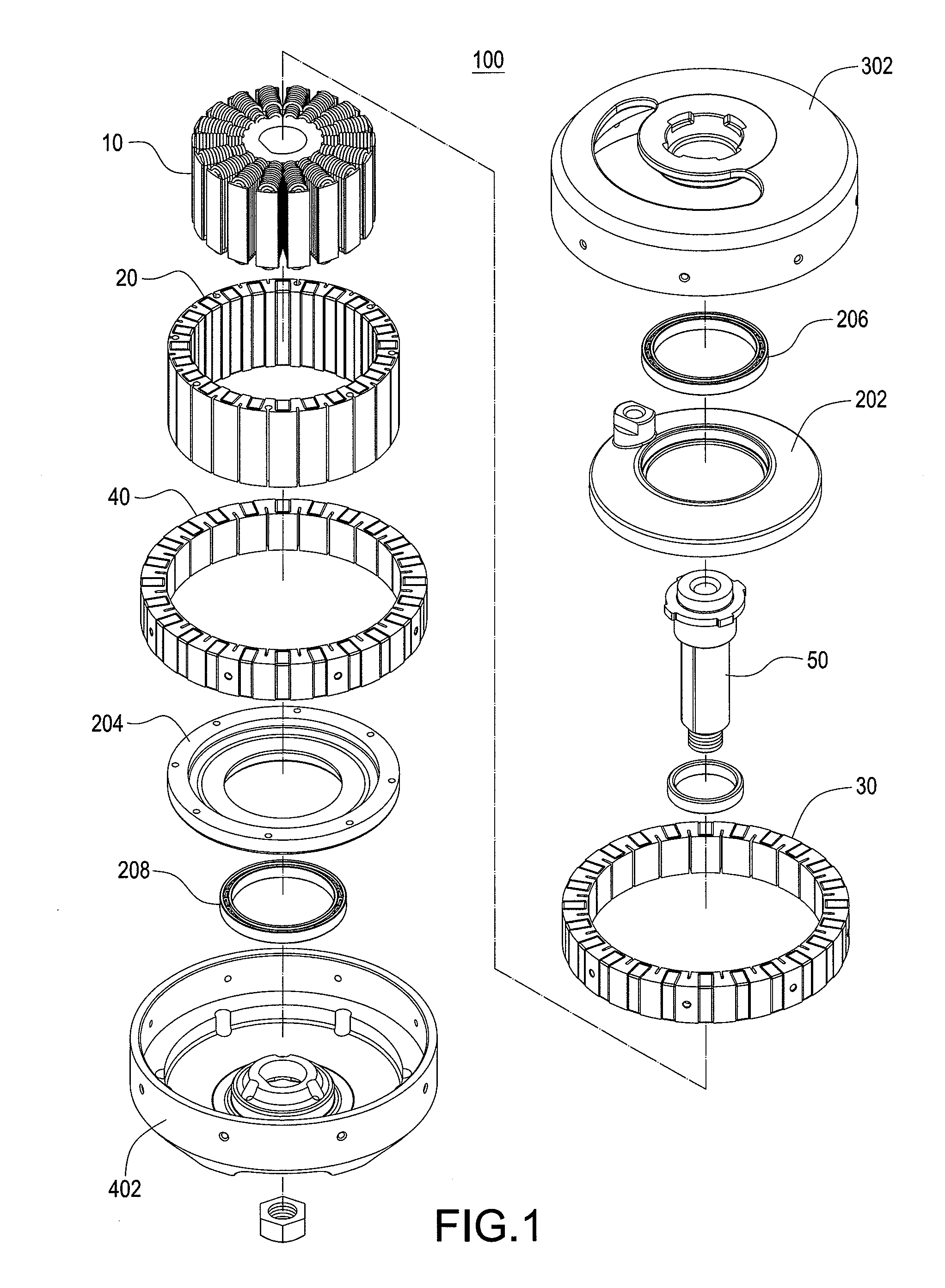
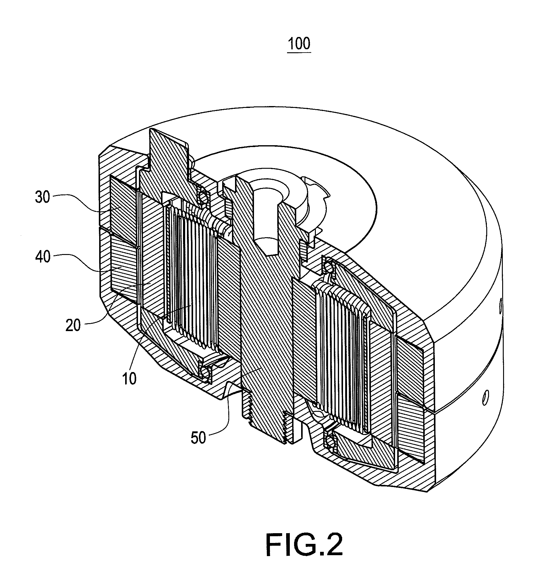
[0033]Reference is made to FIG. 1 and FIG. 2 which are an exploded view and a cross-sectional view of a magnetic-controlled actuator with an auto-locking function for joints of a manipulation arm according to the present invention, respectively. The magnetic-controlled actuator mainly includes an inner-layer stator 10, an inner-layer mover 20, an outer-layer mover 30, an outer-layer stator 40, and a fixed shaft 50.

[0034]The inner-layer stator 10 includes a core 102 and a winding 104 which is winded on the core 102. The inner-layer stator 10 is a multi-pole stator. The inner-layer mover 20 surrounds an outer diameter of the inner-layer stator 10, and the inner-layer mover 20 is formed by alternatively installing a plurality of N-pole permanent magnets (not labeled), a plurality of S-pole permanent magnets (not labeled), and a plurality of iron materials (not labeled). The inner-layer m...


PUM


Abstract

A magnetic-controlled actuator (100) with an auto-locking function for joints of a manipulation arm mainly includes an inner-layer stator (10), an inner-layer mover (20), an outer-layer mover (30), an outer-layer stator (40), and a fixing shaft (50). The inner-layer mover (20), the outer-layer mover (30), and the outer-layer stator (40) have a plurality of permanent magnets, respectively. The fixed shaft (50) simultaneously penetrates through the inner-layer stator (10), the inner-layer mover (20), the outer-layer mover (30), and the outer-layer stator (40) forming a coaxial arrangement. The inner-layer mover (20) rotates relatively to the inner-layer stator (10) to output power from the actuator (100). Therefore, a cogging effect, which is produced due to interaction of the permanent magnets between the outer-layer mover (30) and the outer-layer stator (40), is automatically produces a high cogging torque for the actuator (100). Thus the actuator (100) provides a sufficient locking force to lock the non-stationary inner-layer mover (20) when a power failure occurs.

Description

BACKGROUND OF THE INVENTION[0001]1. Field of the Invention[0002]The present invention relates to an actuator for joints of a manipulation arm, and more particularly to a magnetic-controlled actuator with an auto-locking function for joints of a manipulation arm.[0003]2. Description of Prior Art[0004]In 1984, the International Organization for Standardization gave a definition of robot in ISO 8373, which defined a robot as “an automatically controlled, reprogrammable, multipurpose, manipulator programmable in three or more axes, which may be either fixed in place or mobile for use in industrial automation applications.” In 1994, an industrial robot is officially defined as an automatically controlled, reprogrammable, multipurpose manipulator programmable in three or more axes. The robot should include the manipulator, actuator, and control system of software and hardware. In general, an industrial robot has a manipulator and a memory device, and the latter could be a variable-sequenc...

Claims


Application Information

Patent Timeline
Patent Type & Authority Applications(United States)
IPC IPC(8): H02P15/00H02K16/00
CPCH02K7/12H02K21/029H02K29/03H02K21/42H02K21/22
Inventor HSU, LIANG-YIWANG, PO-KUNGTSAI, MI-CHINGCHENG, MING-YANGHUANG, CHIEN-CHINTSAI, CHING-SHIONGSHEU, HONG-CHENG
Owner DELTA ELECTRONICS INC
Why Eureka
Try Eureka