Power tool

a technology of power tools and locking parts, applied in the field of power tools, can solve the problems of reducing reducing the pressing force of the locking member, and high cogging torque, so as to reduce the pressing force, and improve the operation of the locking member.

Active Publication Date: 2022-05-17
MAKITA CORP
View PDF9 Cites 1 Cited by
  • Summary
  • Abstract
  • Description
  • Claims
  • Application Information

AI Technical Summary

Benefits of technology

[0004]Among other motors, brushless motors tend to include permanent magnets with a high magnetic force. Such brushless motors may generate high cogging torque and further deteriorate the operation of the locking member. A spring may be used to urge the locking member in the unlocking direction. The user may simply reduce the pressing force to allow the locking member to automatically return to its unlock position. A stiffer spring can forcibly return the locking member to the unlock position against the friction due to cogging torque. However, the user may have difficulty in pressing the locking member and have lower operability.

Problems solved by technology

Such brushless motors may generate high cogging torque and further deteriorate the operation of the locking member.
However, the user may have difficulty in pressing the locking member and have lower operability.

Method used


Image

  • Power tool
  • Power tool
  • Power tool

Examples


first embodiment

Power Tool

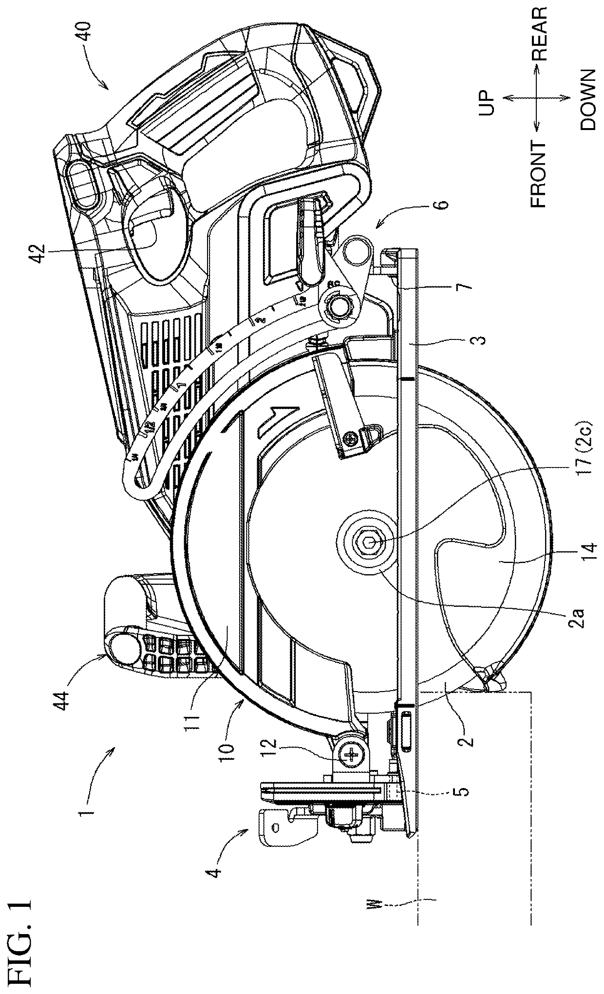
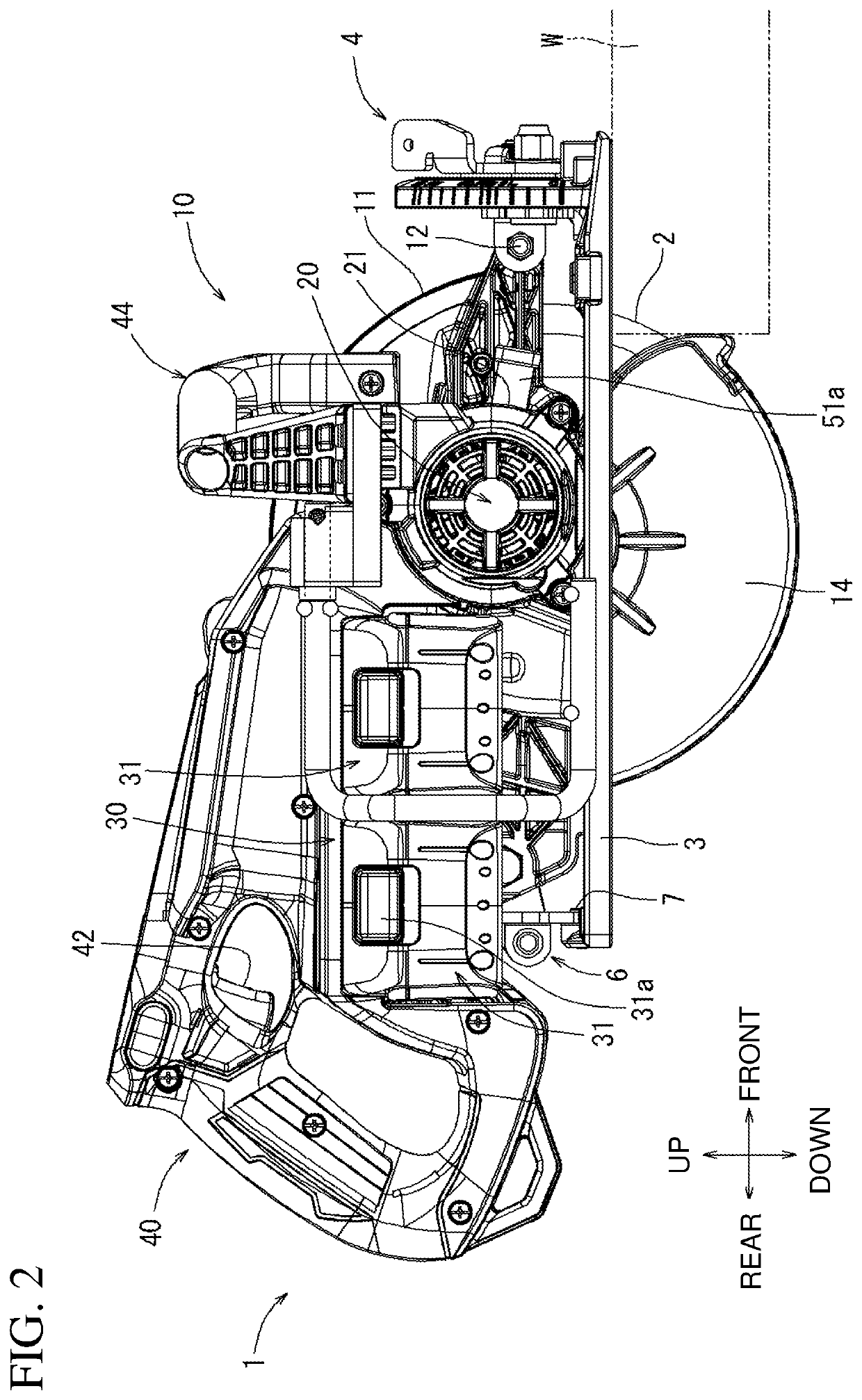
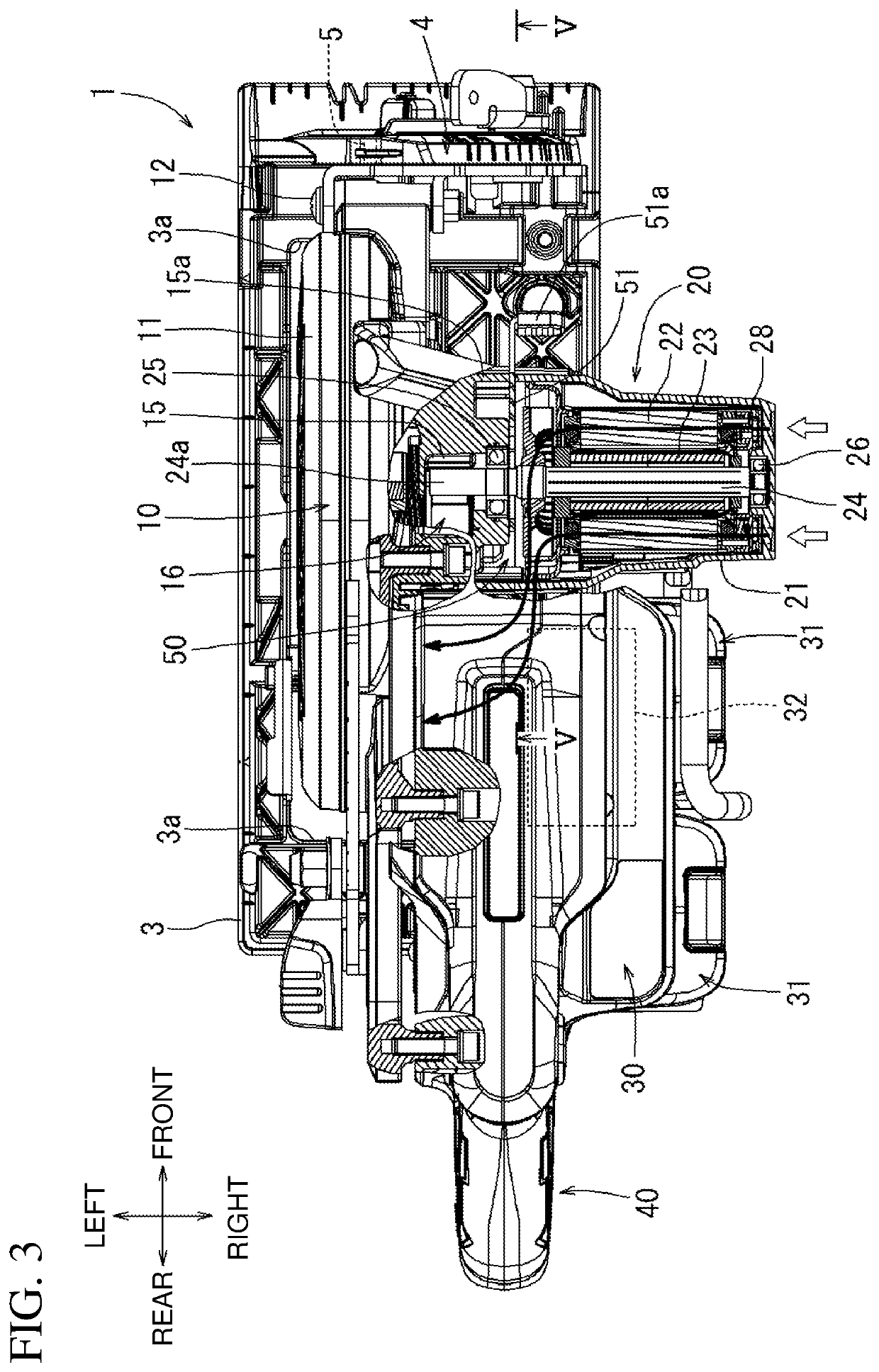
[0028]FIGS. 1 to 3 show a portable circular saw 1 as a power tool according to a first embodiment. A portable circular saw is a portable cutting machine that is a cutting power tool portable by an operator. Other examples of portable cutting machines include a cutter. The portable circular saw 1 includes a tool body 10 and a base 3. The base 3 supports the tool body 10. A circular saw blade 2 (tip tool) is attachable to and detachable from the tool body 10. The saw blade 2 is rotated by an electric motor 20 serving as a driving source incorporated in the tool body 10. The base 3 has a window 3a opening through it in the vertical direction. The saw blade 2 has a lower portion protruding downward from the base 3 through the window 3a. To cut a workpiece W, the user places the base 3 on the upper surface of the workpiece W and cuts into the workpiece W with the saw blade 2 protruding downward from the base 3.

[0029]Although a portable circular saw as an example of a power tool...

second embodiment

[0050]As shown in FIG. 7, the shaft locking mechanism 50 according to the present embodiment includes a protruding portion 51h protruding outward from the surrounding wall 15c, in place of the stepped screw 53. The surrounding wall 15c has a guiding cutout 15h. The cutout 15h receives the protruding portion 51h. The protruding portion 51h and the cutout 15h guide the movement of the locking member 51 between the lock position and the unlock position.

third embodiment

[0051]As shown in FIG. 8, the shaft locking mechanism 50 according to the present embodiment includes two rubber pins 55 and 56 at both sides of the operable member 51a, in place of the single rubber pin 54 and the long hole 51f. The two rubber pins 55 and 56 push the sides of the locking member 51 back against the clockwise and the counterclockwise cogging torque. The rubber pins 55 and 56, which are located adjacent to the surrounding wall 15c, facilitate generation of torque against cogging torque. The two rubber pins 55 and 56 also share the load of torque in different directions between them and allow the locking member 51 to have a simpler shape.


PUM

PropertyMeasurementUnit
rotation angleaaaaaaaaaa
angleaaaaaaaaaa
forceaaaaaaaaaa

Abstract

Twisting of a locking member due to cogging torque is reduced without lowering the locking and unlocking operability for a user. A power tool includes a housing, an electric motor located inside the housing and including a permanent magnet, a shaft rotatable about an axis relative to the housing to transmit power from the electric motor, a locking member movable between a lock position and an unlock position in a nonenergized state of the electric motor and engageable with the shaft at the lock position to lock rotation of the shaft, and an abutting member that applies, to the locking member at the lock position, a force in a direction opposite to an axial torque caused by the permanent magnet and applied to the locking member.

Description

CROSS-REFERENCE TO RELATED APPLICATIONS[0001]This application claims the benefit of priority to Japanese Patent Application No. 2019-096021, filed on May 22, 2019, the entire contents of which are hereby incorporated by reference.BACKGROUND1. Technical Field[0002]The present invention relates to a power tool.2. Description of the Background[0003]A power tool that rotates a tip tool such as a saw blade for machining includes a shaft locking mechanism used to lock the rotation of a spindle when the tip tool is attached to or detached from the spindle. The shaft locking mechanism typically includes a locking member to be engaged with a power transmission shaft such as a motor shaft or the spindle. The user presses the locking member inward or otherwise forces it to be engaged with the shaft to lock the rotation. Some power tools incorporate an electric motor that includes permanent magnets. When the motor is nonenergized, the permanent magnets and teeth with wires wound around them att...

Claims


Application Information

Patent Timeline
Patent Type & Authority Patents(United States)
IPC IPC(8): B23D45/16B23D51/16B27B5/38B27B5/32H02K7/00H02K7/14B27B5/36
CPCB23D45/16B23D51/166B27B5/32B27B5/38H02K7/003H02K7/145B27B5/36B25F5/02
Inventor KANI, TOSHIYUKIGOTO, HIROMUHAMADA, KENJIMURAKAMI, MASAKI
Owner MAKITA CORP
Why Eureka
Try Eureka