Buck-Boost Converter Using Timers for Mode Transition Control

a converter and timer technology, applied in the field of switching regulators, can solve the problems of small glitches in the output voltage vout, and inductor current and output voltage ripple to undesirably increas

Active Publication Date: 2012-02-09
MICREL
View PDF3 Cites 83 Cited by
  • Summary
  • Abstract
  • Description
  • Claims
  • Application Information

AI Technical Summary

Problems solved by technology

A fundamental problem of the buck-boost converter is to determine the appropriate converter behavior when the converter is crossing between the Buck and Buck-Boost operation modes and also between the Buck-Boost and the Boost operation modes in either direction.
This non-repetitive nature in the buck mode, at a time when the input voltage falls to a level approximately equals the output voltage, would cause the inductor current and output voltage ripple to undesirably increase if no remedial measure is taken.
If the input to output voltage ratio then demands a longer on time for switch S3, then a repetitive fixed frequency operation would be broken and switch S3 would be completely off for some periods and on for others, and the inductor current and output voltage ripple would undesirably increase.
However, in reality, the operation of the conventional buck-boost converters is such that transitions between different operation modes result in small glitches in the output voltage Vout due to the lack of a constant, repetitive, fixed frequency operation of the converter.
This oscillating behavior between two operation modes is undesirable but is seen on many of the converter devices commercially available today.
Conventional buck-boost converters are not able to realize smooth transitions into and out of the Buck-Boost mode.

Method used


Image

  • Buck-Boost Converter Using Timers for Mode Transition Control
  • Buck-Boost Converter Using Timers for Mode Transition Control
  • Buck-Boost Converter Using Timers for Mode Transition Control

Examples


Embodiment Construction

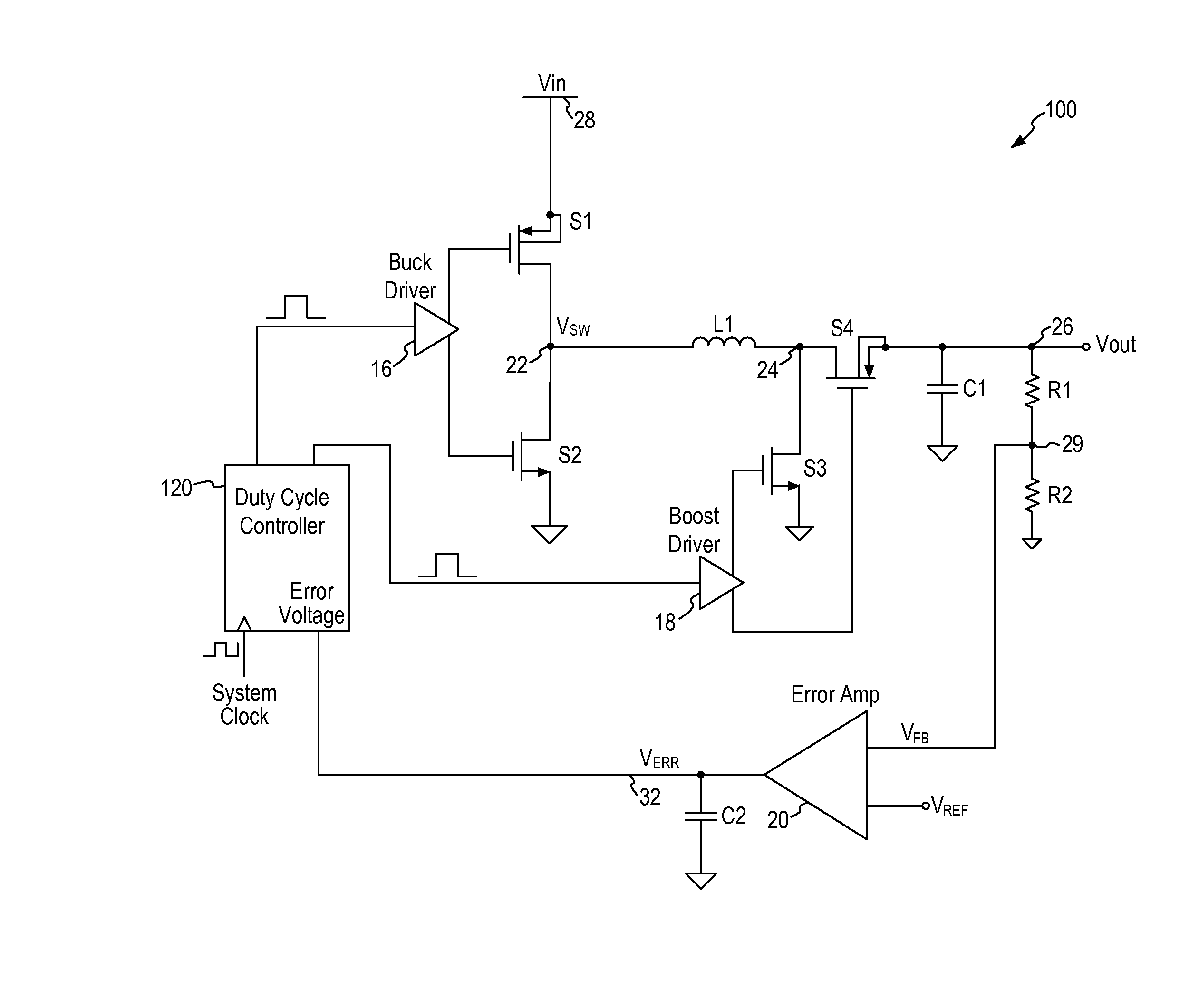
[0033]In accordance with the principles of the present invention, a buck-boost converter incorporates a duty cycle controller using timers to control the transition between Buck, Buck-Boost and Boost modes. More specifically, the timers in the duty cycle controller measure the duty cycle of the buck and boost power switches to determine the transition between the different operation modes. In embodiments of the present invention, a duty cycle timer and an offset timer are used to establish the transition thresholds between the operation modes. Furthermore, in some embodiments, hysteresis is implemented using the offset timer to prevent chattering or transient jumping between the operation modes.

[0034]When a buck-boost converter crosses over the boundary of different operation modes, the duty cycle of the converter must be well controlled in order to avoid chaotic or unwanted behavior. According to embodiments of the present invention, the duty cycle controller in the buck-boost conv...


PUM


Abstract

A DC-to-DC, buck-boost voltage converter includes a duty cycle controller configured to generate control signals for a buck driver configured to drive first and second buck switching transistors at a buck duty cycle and to generate control signals for a boost driver configured to drive first and second boost switching transistors at a boost duty cycle. The duty cycle controller includes at least a duty cycle timer and an offset timer where the duty cycle controller applies the duty cycle timer and the offset timer to control transitions between the buck, the buck-boost and the boost operation modes of the voltage converter.

Description

CROSS-REFERENCE TO RELATED APPLICATION[0001]This application is a continuation-in-part of application Ser. No. 12 / 546,602, filed on Aug. 24, 2009, entitled “Buck-Boost Converter With Smooth Transitions Between Modes” of David Dearn, which application is incorporated herein by reference in its entirety.FIELD OF THE INVENTION[0002]The invention relates to switching regulators and, in particular, to a buck-boost converter using timer to realize smooth transitioning between operation modes.DESCRIPTION OF THE RELATED ART[0003]Switch mode power supplies or switching regulators, also referred to as DC-to-DC converters, are often used to convert an input supply voltage to a desired output voltage. A switching regulator provides power supply function through low loss components such as capacitors, inductors, and transformers, and power switches that are turned on and off to transfer energy from the input to the output in discrete packets. A feedback control circuit is used to regulate the en...

Claims


Application Information

Patent Timeline
Patent Type & Authority Applications(United States)
IPC IPC(8): G05F1/56
CPCH02M3/1582
Inventor CASEY, CHARLES A.DEARN, DAVID
Owner MICREL
Why Eureka
Try Eureka