
Shutter glasses and method for controlling a pair of shutter glasses

a technology of shutter glasses and control glasses, applied in the field of stereo image viewing, can solve the problems of reducing the quality of the stereo image the user views, increasing the power consumption of the pair of shutter glasses accordingly, and affecting the viewing experience of users, so as to reduce the power consumption of the pair of shutter glasses effectively, increase the ambient brightness of users, and reasonable image quality

Inactive Publication Date: 2012-02-09
ACER INC
View PDF3 Cites 8 Cited by
  • Summary
  • Abstract
  • Description
  • Claims
  • Application Information

AI Technical Summary

Benefits of technology

[0009]Therefore, one of the objectives of the present invention is to provide a pair of shutter glasses and a method for controlling the pair of shutter glasses, which can provide a reasonable image quality when the user is viewing stereo images presented by the video output apparatus, and lengthen the shutter-on period of the shutter lens of the pair of shutter glasses to thereby increase the ambient brightness users feel and / or decrease power consumption of the pair of shutter glasses effectively.

Problems solved by technology

However, if the shutter-on period of the shutter lens is not properly controlled, the user's left eye may probably see part of the right-eye image and / or the user's right eye may probably see part of the left-eye image, which significantly degrades the quality of the stereo image the user views.
If the user feels lack of ambient brightness when wearing the pair of shutter glasses, he / she may not identify items, such as a keyboard or remote control, beyond the screen of the video output apparatus clearly, leading to inconvenience in stereo image viewing for users.
Thus, if the shutter lens stays in an off-state longer, the power consumption of the pair of shutter glasses is increased accordingly.

Method used


Image

  • Shutter glasses and method for controlling a pair of shutter glasses
  • Shutter glasses and method for controlling a pair of shutter glasses
  • Shutter glasses and method for controlling a pair of shutter glasses

Examples


Embodiment Construction

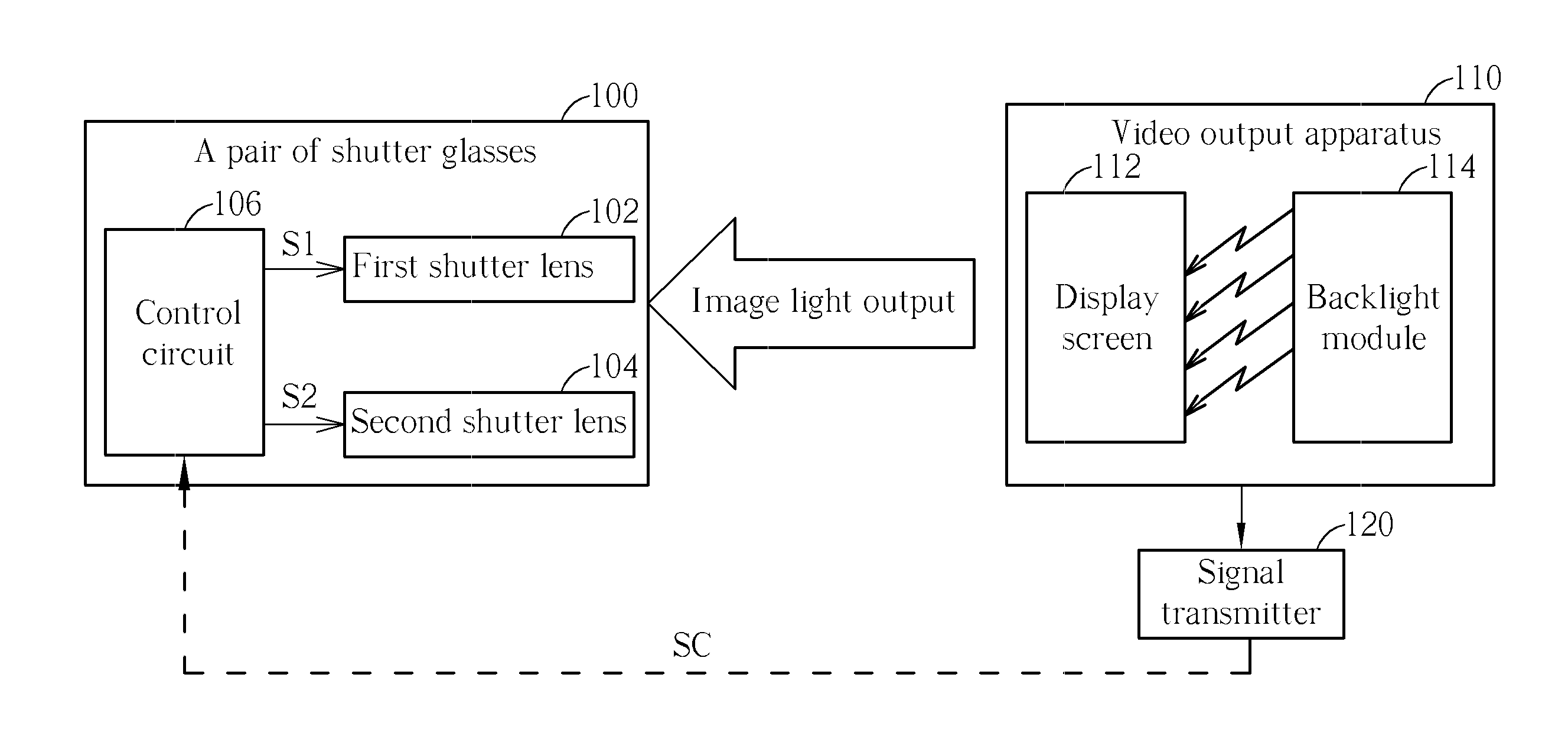
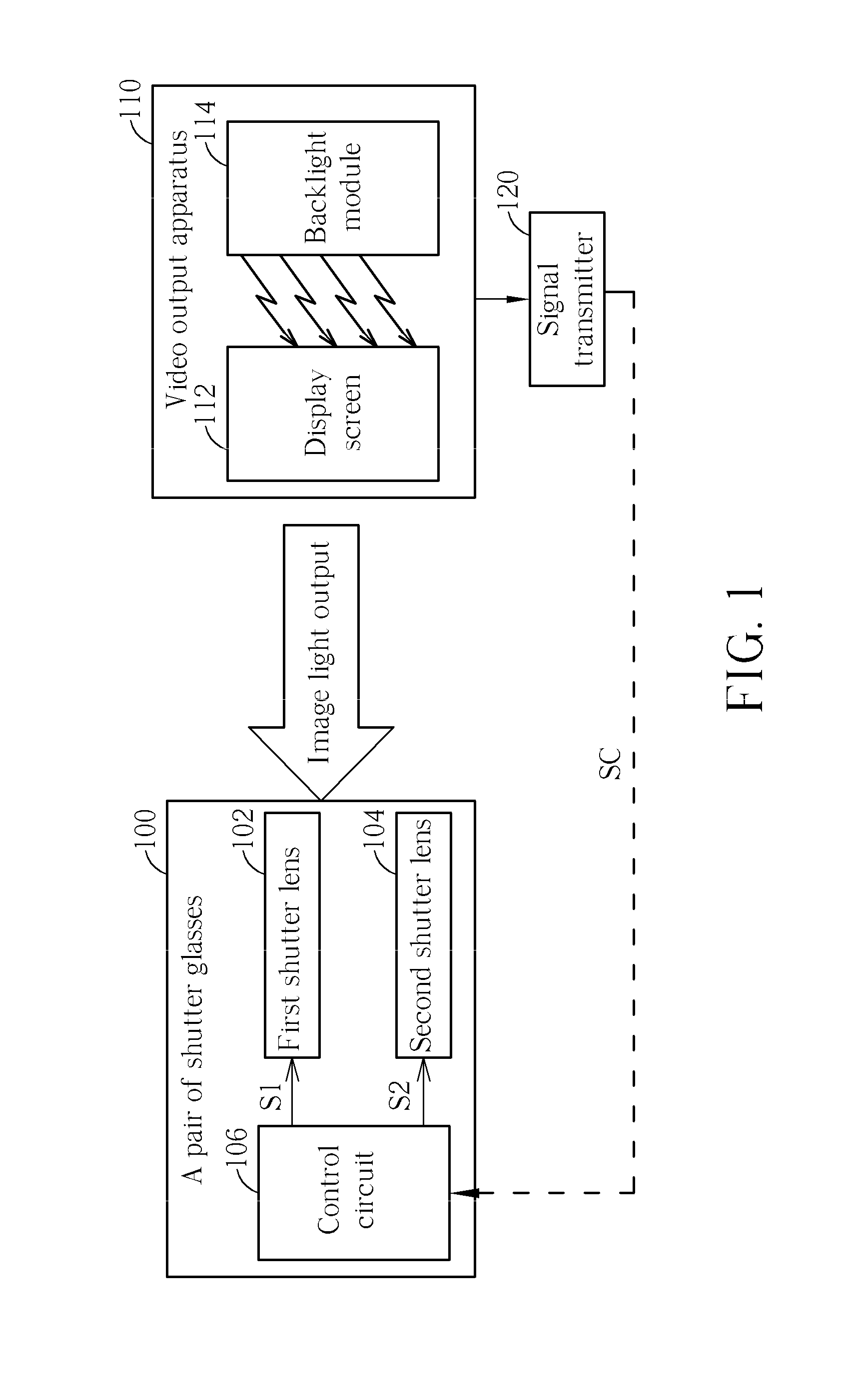
[0026]Please refer to FIG. 1, which is a function block diagram of a pair of shutter glasses utilized for viewing stereo images presented by a video output apparatus. In present exemplary embodiment, pair of shutter glasses 100 comprises, but is not limited to, a first shutter lens 102, a second shutter lens 104 and a control circuit 106. One of the first shutter lens 102 and second shutter lens 104 (e.g., the first shutter lens 102) is utilized for viewing left-eye images, and the other one of the first shutter lens 102 and the second shutter lens 104 (e.g., the second shutter lens 104) is utilized for viewing right-eye images. Besides, the control circuit 106 respectively outputs control signals S1 and S2 to the first shutter lens 102 and the second shutter lens 104, in order to control the first shutter lens 102 to be switched between an on-state (or called open state) and an off-state (or called a close state), and control the second shutter lens 104 to be switched between an on...


PUM


Abstract

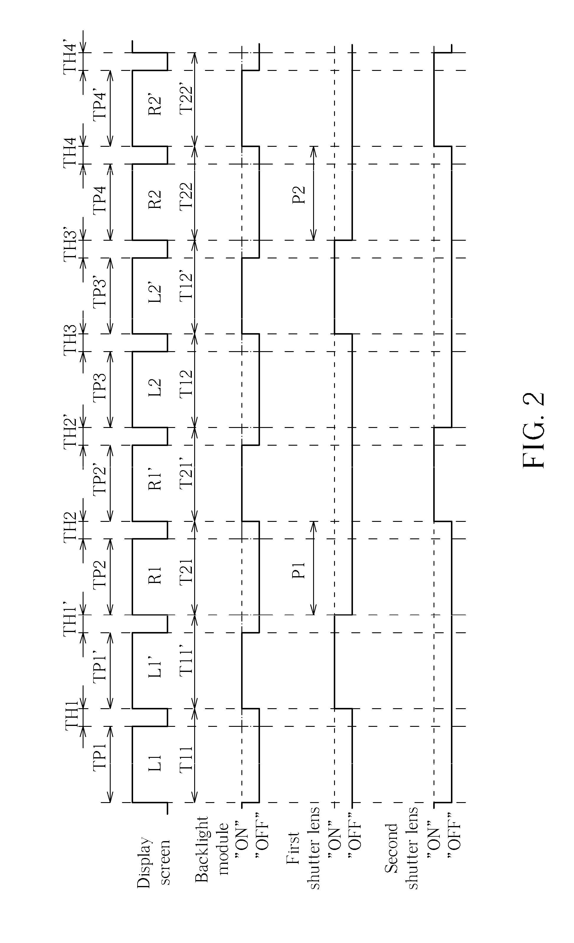
A method for controlling shutter glasses includes controlling each of a first shutter lens and a second shutter lens to be switched between an on-state and an off-state, wherein the first shutter lens stays in the on-state within an image output period corresponding to a secondary first image, and stays in the off-state with an image output period corresponding to a following primary second image, and the second shutter lens stays in the off-state within the image output period corresponding to the primary second image, and stays in the on-state within an image output period corresponding to a following secondary second image. The first shutter lens and the second shutter lens simultaneously stay in the off-state only within a single continuous time period of the image output period corresponding to the primary second image.

Description

BACKGROUND OF THE INVENTION[0001]1. Field of the Invention[0002]The present invention relates to a technique of viewing stereo images, and more particularly, to a pair of shutter glasses utilized for viewing stereo images presented by a video output apparatus and a method for controlling the pair of shutter glasses.[0003]2. Description of the Prior Art[0004]With the development of science and technology, users are pursing stereoscopic and more real image displays rather than high quality images. There are two techniques of present stereo image display. One is to use a video output apparatus which collaborates with glasses (such as anaglyph glasses, polarization glasses or shutter glasses), while the other one to directly use a video output apparatus without any accompanying glasses. No matter which technique is utilized, the main theory of stereo image display is to make the left eye and the right eye see different images, thus the brain will regard the different images seen from tw...

Claims


Application Information

Patent Timeline
IPC IPC(8): H04N13/04
CPCH04N13/0438H04N13/341
Inventor KO, CHUEH-PIN
Owner ACER INC
Learn More