

Network system
- Summary
- Abstract
- Description
- Claims
- Application Information
AI Technical Summary
Benefits of technology
Problems solved by technology
Method used
Image

Examples
first embodiment
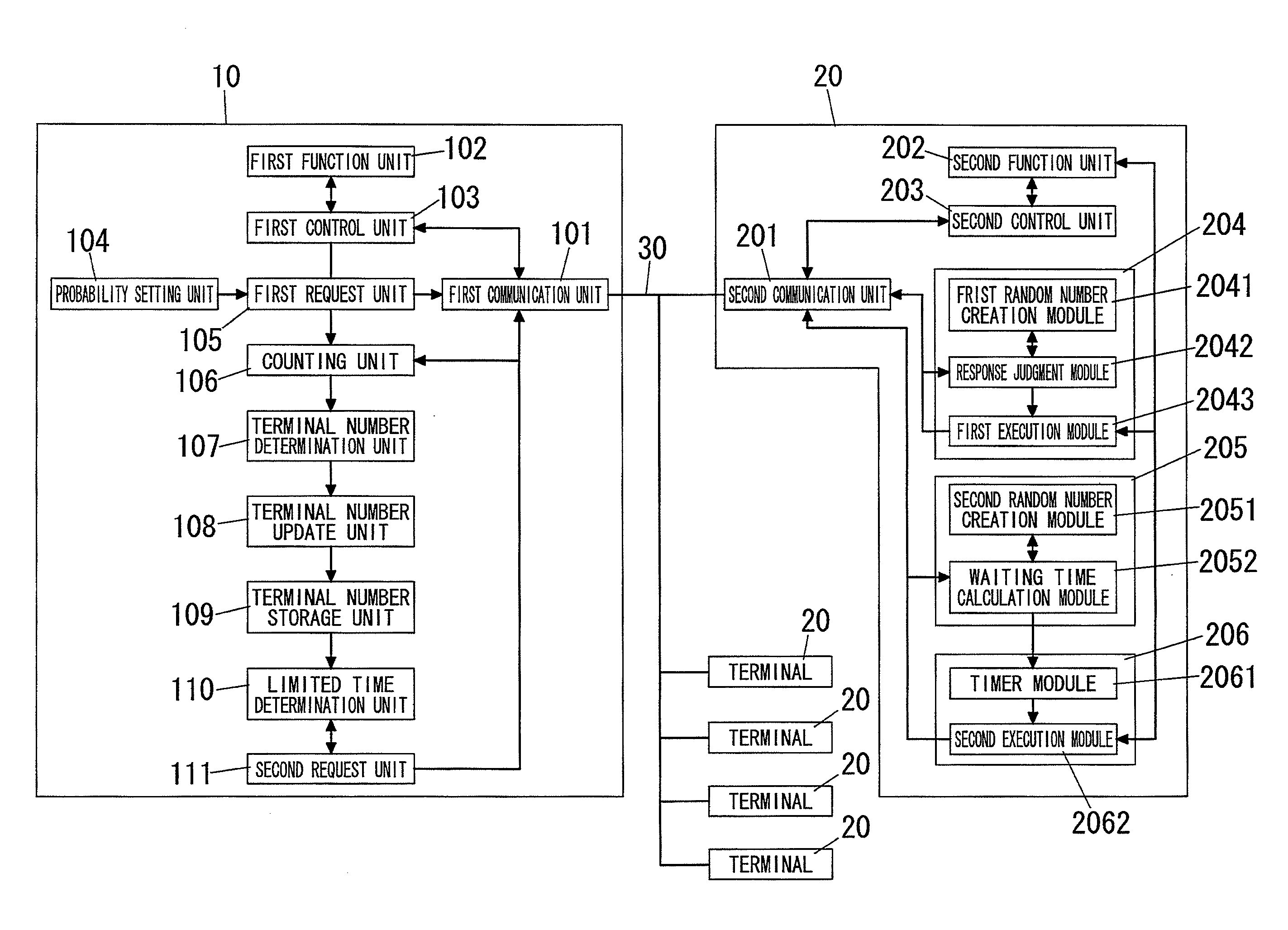
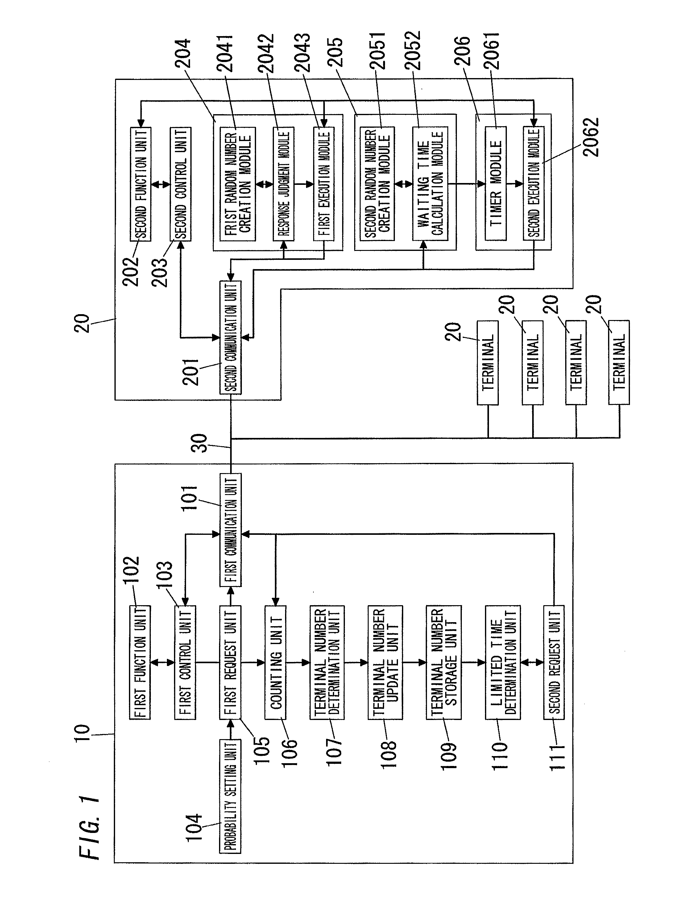
[0025]FIG. 1 shows a configuration of the network system of the present embodiment. The network system of the present embodiment includes a controller (multicast terminal device) 10 and a plurality of terminals 20 connected to the controller 10 via a network 30. In the present network system, plural terminal devices (the controller 10 and terminals 20) are connected to the network 30, and communicate with each other. For example, each of the controller 10 and terminals 20 comprises a microcomputer including such as a memory, a processor, and an interface adapted in use to be connected to the network 30. Besides, the network 30 may be a wired network or a wireless network.
[0026]The controller 10 is configured to monitor and control each of the terminals 20. In more detail, the controller 10 sends a request signal (response requesting command) to each of the terminals 20. The request signal is a multicast packet such as a request signal for controlling the terminal 20, a request signa...
second embodiment
[0114]FIG. 8 illustrates the network system of the present embodiment. The network system of the present embodiment includes the controller 10B and the plurality of terminals 20B connected to the controller 10B via the network 30. Components common to the network systems of the first and present embodiments are designated by same reference numerals, and no explanations thereof are deemed necessary.
[0115]The controller 10B includes the first communication unit 101, the first function unit 102, and the first control unit 103, the probability setting unit 104, the first request unit 105B, the counting unit 106B, the terminal number determination unit 107B, the limited time determination unit 110B, the second request unit 111B, and a responding terminal storage unit 114.
[0116]The terminal 20B includes the second communication unit 201, the second function unit 202, the second control unit 203, the first response unit 204, the waiting time determination unit 205B, the second response uni...
PUM
 Abstract
Description
Claims
Application Information