Virtual IP interfaces on multi-chassis link aggregates

Active Publication Date: 2012-02-09
WSOU INVESTMENTS LLC
View PDF2 Cites 159 Cited by
  • Summary
  • Abstract
  • Description
  • Claims
  • Application Information

AI Technical Summary

Problems solved by technology

One of the key challenges faced by data networks is the need for network resiliency, i.e., the ability to maintain high availability despite eventual component failures, link failures or the like, which is critical to providing satisfactory network performance.
However, STP can result in unacceptable convergenc

Method used


Image

  • Virtual IP interfaces on multi-chassis link aggregates
  • Virtual IP interfaces on multi-chassis link aggregates
  • Virtual IP interfaces on multi-chassis link aggregates

Examples


Embodiment Construction

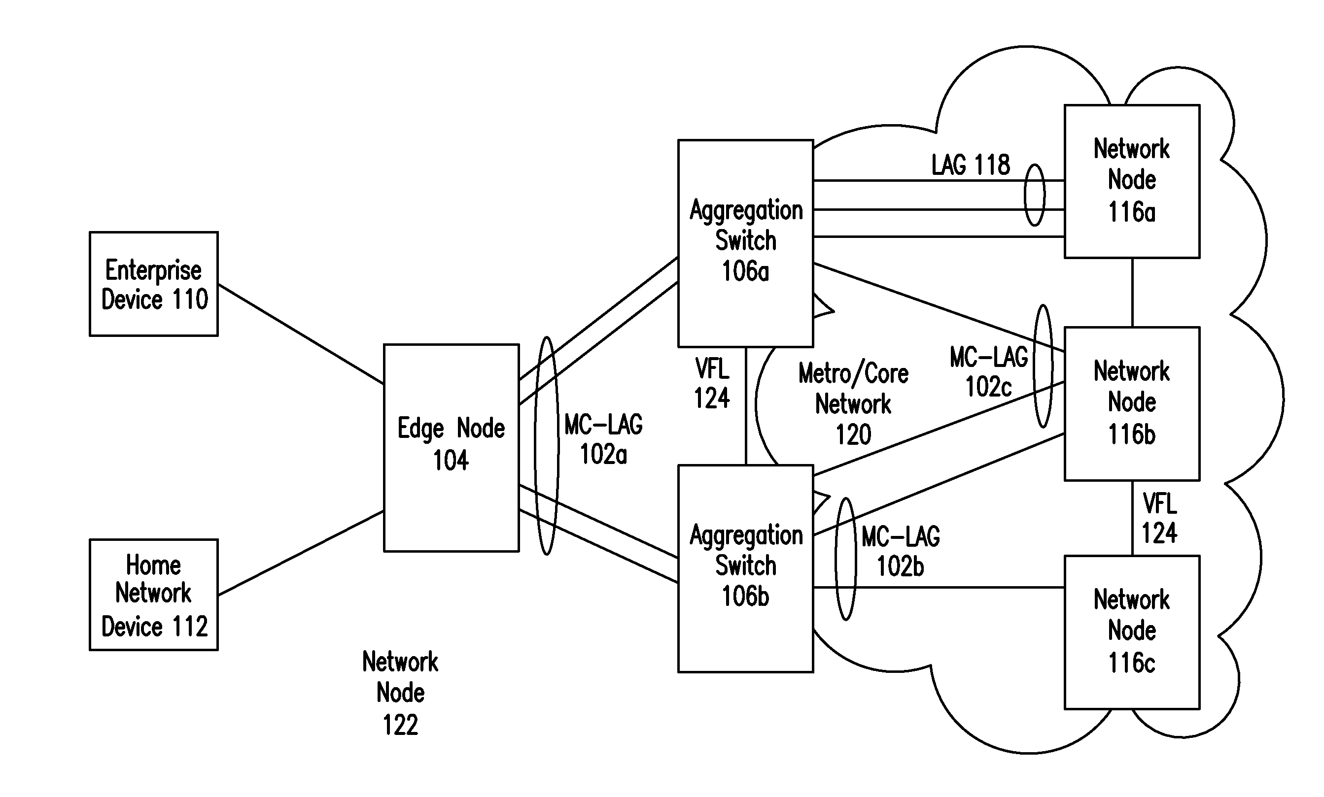
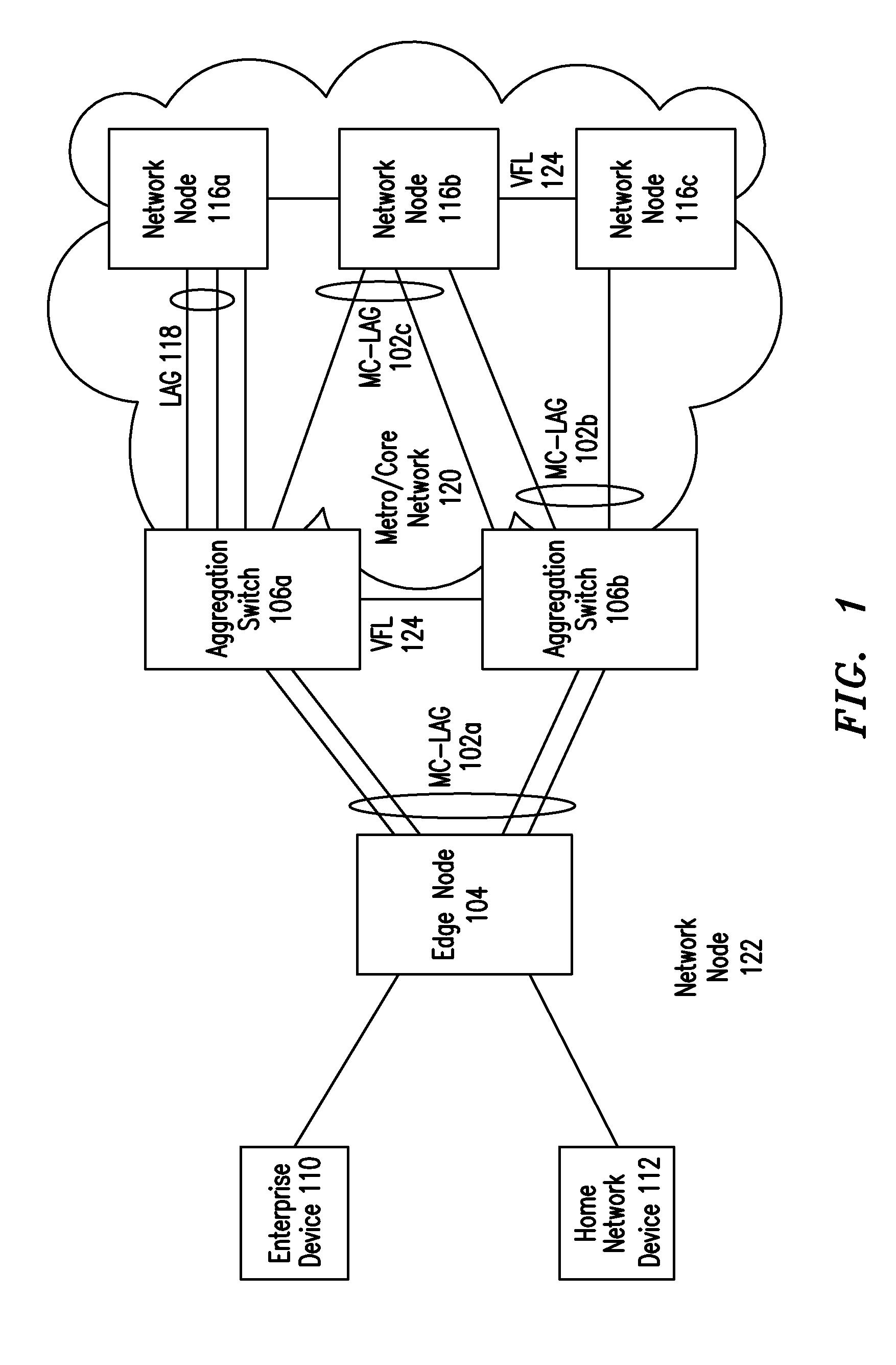
[0028]FIG. 1 illustrates an embodiment of a resilient network 100 with multi-chassis link aggregation that provides an active / active paradigm (i.e., all links actively forwarding traffic at the same time) that more fully utilizes the capacity of the network nodes. The following abbreviations are herewith defined:

CMM Chassis Management Module

IGMP Internet Group Management Protocol

IP Internet Protocol

IPMS Internet Protocol Multicast

LAG Link Aggregation

[0029]L2 Layer 2 (“Data Link Layer”) of the OSI model for networks

L3 Layer 3 (“Network Layer”) of the OSI model for networks

MAC Media Access Control Protocol

MC-LAG Multi-Chassis Link Aggregate Group

MC-VFA Multi-Chassis Virtual Fabric Aggregation

NIM Network Interface Module

STP Spanning Tree Protocol

VLAN Virtual Local Area Network

VRRP Virtual Router Redundancy Protocol

ASIC Application Specific Integrated Circuit

[0030]The following standards are referred to in this application and are incorporated by reference herein: 1) the Link Aggregatio...


PUM


Abstract

Aggregation Switches connected via a virtual fabric link (VFL) are each active and each coupled to a multi-chassis link aggregate group (MC-LAG), which is assigned to a multi-chassis link aggregate group virtual local area network (MC-LAG VLAN). A virtual Internet Protocol (IP) interface is allocated to the MC-LAG VLAN and configured on both Aggregation Switches

Description

CROSS-REFERENCE TO RELATED PATENTS[0001]The present U.S. Utility patent application claims priority pursuant to 35 U.S.C. §119(e) to U.S. Provisional Application Ser. No. 61 / 370,622, entitled, “MULTI-CHASSIS VIRTUAL-FABRIC LINK AGGREGATION SYSTEM,” filed Aug. 4, 2010, which is incorporated by reference herein and made part of the present U.S. Utility patent application for all purposes.STATEMENT REGARDING FEDERALLY SPONSORED RESEARCH OR DEVELOPMENT[0002]Not Applicable.INCORPORATION-BY-REFERENCE OF MATERIAL SUBMITTED ON A COMPACT DISC[0003]Not applicable.BACKGROUND OF THE INVENTION[0004]1. Technical Field of the Invention[0005]This invention relates generally to data networks and in particular to systems and methods for providing IP multicast snooping and routing.[0006]2. Description of Related Art[0007]Data networks allow many different computing devices, for example, personal computers, IP telephony devices or servers to communicate with each other and / or with various other network...

Claims


Application Information

Patent Timeline
IPC IPC(8): H04L12/28H04L12/56H04L45/74H04L45/24H04L45/243H04L45/28H04L45/586H04L47/41
CPCH04L45/22H04L45/245H04L45/586H04L49/552Y02B60/33H04L45/28Y02D30/50H04L45/54
Inventor PAGE, GREGORY G.DIGHE, SAHIL P.JACOB DA SILVA, ROBERTO H.JONES, BRUCE R.TYAMAGONDLU, SRINIVAS V.
Owner WSOU INVESTMENTS LLC
Why Eureka
Try Eureka