Blade monitoring system

a blade monitoring and blade technology, applied in the field of turbines, can solve the problems of excessive high cycle and low cycle fatigue, gas turbine compressor blade damage, and parts of gas turbine compressors

Active Publication Date: 2012-02-09
BAKER HUGHES OILFIELD OPERATIONS LLC
View PDF8 Cites 13 Cited by
  • Summary
  • Abstract
  • Description
  • Claims
  • Application Information

AI Technical Summary

Problems solved by technology

Over time, portions of the gas turbine compressor may become damaged.
Gas turbine compressor blades may become damaged, for example, by particles, foreign objects, and / or corrosive elements in the inlet air, as well as excessive high cycle and low-cycle fatigue during compressor operation.
Damage to gas turbine compressor blades may cause inefficiencies in gas turbine operation and / or unwanted vibrations in the compressor.
In some cases, compressor blade damage may cause liberation of one or more blades, resulting in catastrophic damage to the compressor.
Blades within a steam turbine compressor are susceptible to similar damage as described for gas turbine compressors.

Method used


Image

  • Blade monitoring system
  • Blade monitoring system
  • Blade monitoring system

Examples


Embodiment Construction

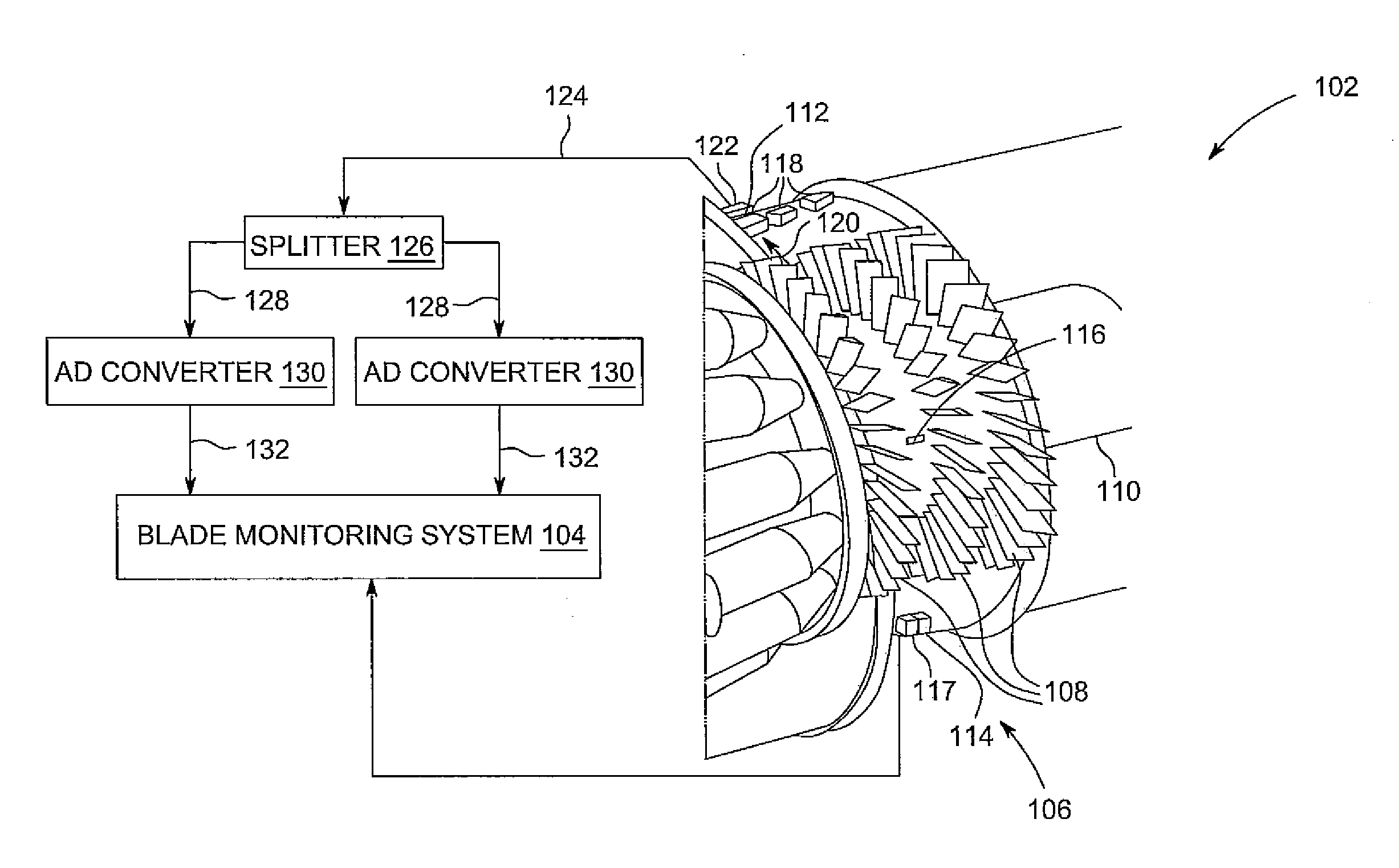
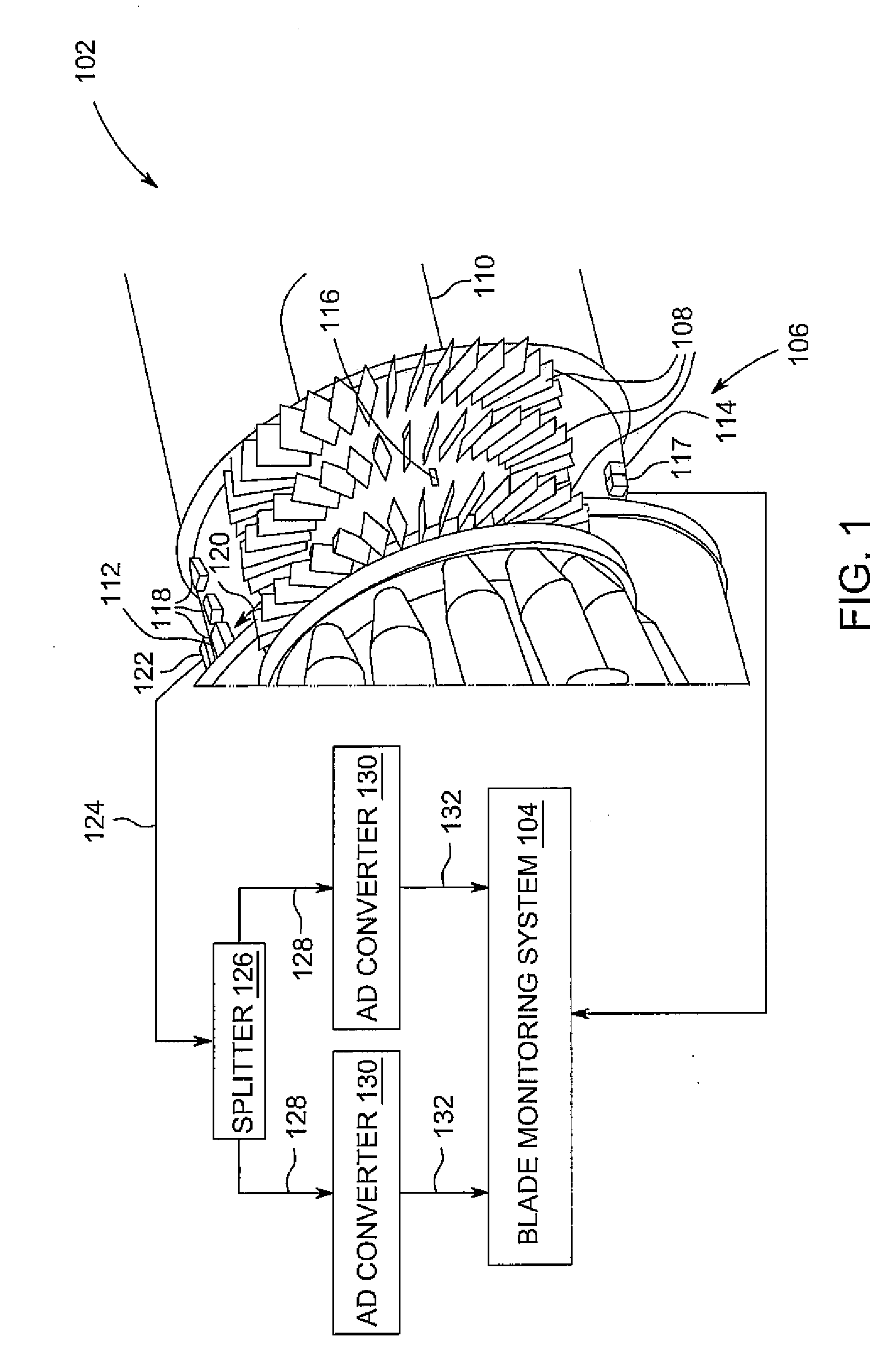
[0014]Referring to FIG. 1, a perspective partial cut-away view of a turbine 102 and one embodiment of a blade monitoring system 104 in accordance with the invention is shown. Turbine 102 is only illustrative; teachings of the invention may be applied to a variety of turbines including gas turbines and steam turbines. In this embodiment, turbine 102 includes a compressor 106 including a plurality of blades 108, and a rotor 110. Blades 108 are attached to rotor 110. Combustion gases in gas turbines or steam in steam turbines propel blades 108. Propelled blades 108 rotate rotor 110. A casing 112 forms an outer enclosure that encloses compressor 106, blades 108, and rotor 110. Blades 108 are shown in rows. Three rows are shown but is only illustrative. Teachings of the invention may be applied to any number of rows of blades 108.

[0015]A once-per-turn (OPT) sensor 114 is shown that, for each turn of the rotor, senses a sensing notch 116 on rotor 110. Sensing notch 116 may cause a voltage...


PUM


Abstract

A system including a turbine including a compressor having at least one row of a plurality of blades; a sensor for sensing a blade passing signal of at least one of the plurality of blades; an analog signal transmitter for transmitting an analog signal for the blade passing signal; a signal splitter for splitting the analog signal into at least two split analog signals; at least two analog-to-digital (AD) converters, each AD converter converting each split analog signal to at least two digital waveform samples; and a blade monitoring system that: calculates at least two interpolated threshold crossings, each interpolated threshold crossing calculated from at least two digital waveform samples from each AD converter; and calculates an average threshold crossing (ATC) of the at least two interpolated threshold crossings.

Description

BACKGROUND OF THE INVENTION[0001]This invention relates generally to turbines and more particularly to a system for blade monitoring in turbines for monitoring of blades for damage.[0002]Compressors, such as gas turbine compressors, receive inlet air from an air source and compress that air so that it may be later combined with fuel in a combustion chamber. The gas created from combustion of the compressed air and fuel mixture is then used to force rotation of blades within the gas turbine compressor, and correspondingly, perform mechanical work on a shaft coupled to those blades. Over time, portions of the gas turbine compressor may become damaged. Gas turbine compressor blades may become damaged, for example, by particles, foreign objects, and / or corrosive elements in the inlet air, as well as excessive high cycle and low-cycle fatigue during compressor operation. Damage to gas turbine compressor blades may cause inefficiencies in gas turbine operation and / or unwanted vibrations i...

Claims


Application Information

Patent Timeline
IPC IPC(8): G06F19/00G01R29/00
CPCF01D21/003F05D2260/80F05D2270/334F04D27/001F04D29/324
Inventor HADLEY, STEVEN ROSSHATCH, CHARLES TERRANCE
Owner BAKER HUGHES OILFIELD OPERATIONS LLC
Why Eureka
Try Eureka